KEY REMINDER WARNING SYSTEM TERMINALS OF ECU
-
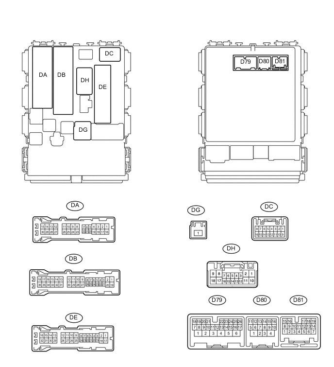
CHECK MAIN BODY ECU (INSTRUMENT PANEL JUNCTION BLOCK ASSEMBLY)
-
Disconnect the DB, DE, DG and D80 ECU connectors.
-
Measure the resistance and voltage according to the value(s) in the table below.
Terminal No. (Symbol) Wiring Color Terminal Description Condition Specified Condition DE-17 (GND1) - Body ground W-B - Body ground Ground Always Below 1 Ω D80-4 (GND2) - Body ground W-B - Body ground Ground Always Below 1 Ω DB-12 (BECU) - Body ground W - Body ground Power source Always 11 to 14 V DG-1 (ALTB) - Body ground W - Body ground DE-23 (KSW) - Body ground L - Body ground Unlock warning switch signal No key in ignition key cylinder 10 kΩ or higher Key in ignition key cylinder Below 1 Ω If the result is not as specified, there may be a malfunction on the wire harness side.
-
Reconnect the DB, DE, DG and D80 ECU connectors.
-
Measure the voltage according to the value(s) in the table below.
Terminal No. (Symbol) Wiring Color Terminal Description Condition Specified Condition DA-21 (DCTY)*1 - Body ground
DC-6 (DCTY)*2 - Body ground
W*1 - Body ground
SB*2 - Body ground
Driver side door courtesy light switch Driver side door closed 11 to 14 V Driver side door open Below 1 V
-
*1: for LHD
-
*2: for RHD
If the result is not as specified, the ECU may have a malfunction.
-
-