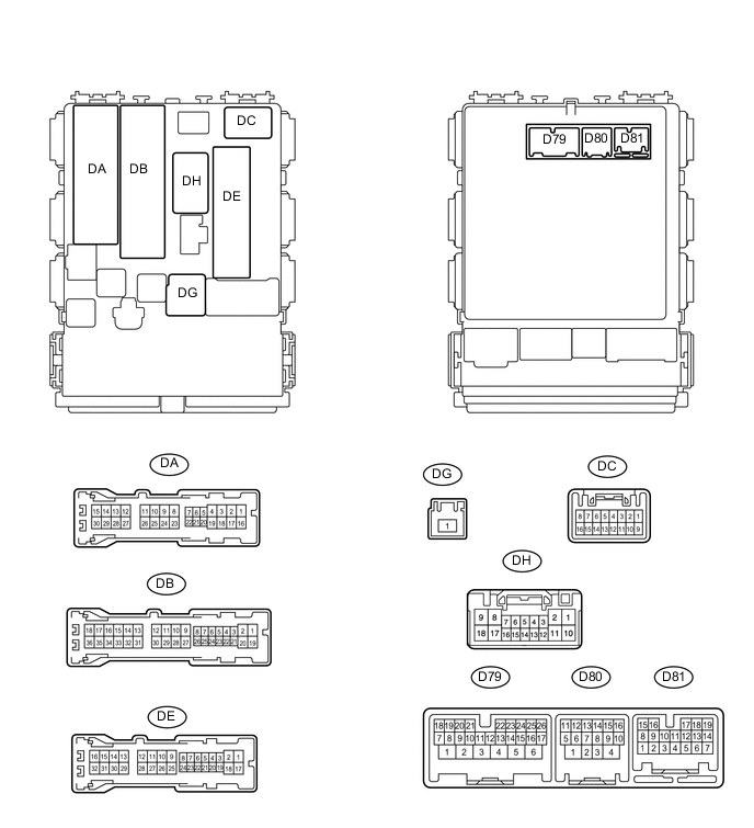
POWER DOOR LOCK CONTROL SYSTEM TERMINALS OF ECU
-
CHECK POWER WINDOW REGULATOR MASTER SWITCH ASSEMBLY

Text in Illustration *1 for LHD *2 for RHD
-
Disconnect the E14*1 or E8*2 switch connector.
-
Measure the voltage and resistance according to the value(s) in the table below.
Terminal No. (Symbol) Wiring Color Terminal Description Condition Specified Condition E14-12 (GND)*1 - Body ground W-B - Body ground Ground Always Below 1 Ω E14-11 (B)*1 - Body ground R - Body ground Battery power supply Always 11 to 14 V E8-12 (GND)*2 - Body ground W-B - Body ground Ground Always Below 1 Ω E8-11 (B)*2 - Body ground R - Body ground Battery power supply Always 11 to 14 V *1: for LHD
*2: for RHD
If the result is not as specified, there may be a malfunction on the wire harness side.
-
-
CHECK MAIN BODY ECU (INSTRUMENT PANEL JUNCTION BLOCK ASSEMBLY)
-
Disconnect the D79, D80, DB, DE and DG ECU connectors.
-
Measure the voltage and resistance according to the value(s) in the table below.
Terminal No. (Symbol) Wiring Color Terminal Description Condition Specified Condition D79-4 (BATB) - Body ground BR - Body ground Battery power supply Always 11 to 14 V DG-1 (ALTB) - Body ground W - Body ground Battery power supply Always 11 to 14 V DB-30 (BECU) - Body ground W - Body ground Power supply Always 11 to 14 V DE-17 (GND1) - Body ground W-B - Body ground Ground Always Below 1 Ω D80-4 (GND2) - Body ground W-B - Body ground Ground Always Below 1 Ω If the result is not as specified, there may be a malfunction on the wire harness side.
-
Reconnect the D79, D80, DB, DE and DG ECU connectors.
-
Measure the voltage according to the value(s) in the table below.
Terminal No. (Symbol) Wiring Color Terminal Description Condition Specified Condition DA-21 (DCTY)*1 - Body ground
DC-6 (DCTY)*2 - Body ground
W*1 - Body ground
SB*2 - Body ground
Driver side door courtesy light switch input Driver side door open Below 1 V DA-21 (DCTY)*1 - Body ground
DC-6 (DCTY)*2 - Body ground
W*1 - Body ground
SB*2 - Body ground
Driver side door courtesy light switch input Ignition switch off and driver side door courtesy light switch off 11 to 14 V DE-20 (PCTY)*1 - Body ground
DA-24 (PCTY)*2 - Body ground
Y*1 - Body ground
W*2 - Body ground
Front passenger side door courtesy light switch input Front passenger side door open Below 1 V DE-20 (PCTY)*1 - Body ground
DA-24 (PCTY)*2 - Body ground
Y*1 - Body ground
W*2 - Body ground
Front passenger side door courtesy light switch input Ignition switch off and passenger side door courtesy light switch off 11 to 14 V D79-8 (LCTY) - Body ground SB - Body ground Rear door LH courtesy light switch input Rear door LH open Below 1 V D79-8 (LCTY) - Body ground SB - Body ground Rear door LH courtesy light switch input Ignition switch off and rear LH side door courtesy light switch off 11 to 14 V DE-19 (RCTY) - Body ground LG - Body ground Rear door RH courtesy light switch input Rear door RH open Below 1 V DE-19 (RCTY) - Body ground LG - Body ground Rear door RH courtesy light switch input Ignition switch off and rear RH side door courtesy light switch off 11 to 14 V DA-7 (BCTY) - Body ground LG - Body ground Luggage room compartment door courtesy light switch input*3
Back door courtesy light switch input*4
Luggage compartment door open*3
Back door open*4
Below 1 V DA-7 (BCTY) - Body ground LG - Body ground Luggage room compartment door courtesy light switch input*3
Back door courtesy light switch input*4
Ignition switch off and luggage compartment door closed*3
Ignition switch off and back door closed*4
11 to 14 V DH-8 (ACT+) - Body ground W - Body ground Front door LH door lock motor lock drive output Master switch (door control switch) or driver side door key cylinder neutral position Below 1 V DH-8 (ACT+) - Body ground W - Body ground Front door LH door lock motor lock drive output Master switch (door control switch) or driver side door key cylinder lock 11 to 14 V DH-17 (ACT+) - Body ground R - Body ground Front door RH, rear door RH door lock motor lock drive output Master switch (door control switch) or driver side door key cylinder neutral position Below 1 V DH-17 (ACT+) - Body ground R - Body ground Front door RH, rear door RH door lock motor lock drive output Master switch (door control switch) or driver side door key cylinder lock 11 to 14 V DA-3 (ACT+) - Body ground R - Body ground Rear door LH door lock motor unlock drive output Master switch (door control switch) or driver side door key cylinder neutral position Below 1 V DA-3 (ACT+) - Body ground R - Body ground Rear door LH door lock motor unlock drive output Master switch (door control switch) or driver side door key cylinder lock 11 to 14 V DH-9 (ACT-) - Body ground LG - Body ground Front door LH door lock motor unlock drive output Master switch (door control switch) or driver side door key cylinder neutral position Below 1 V DH-9 (ACT-) - Body ground LG - Body ground Front door LH door lock motor unlock drive output Master switch (door control switch) or driver side door key cylinder unlock 11 to 14 V DA-4 (ACT-) - Body ground SB - Body ground Rear door LH door lock motor unlock drive output Master switch (door control switch) or driver side door key cylinder neutral position Below 1 V DA-4 (ACT-) - Body ground SB - Body ground Rear door LH door lock motor unlock drive output Master switch (door control switch) or driver side door key cylinder unlock 11 to 14 V DH-18 (ACT-) - Body ground SB - Body ground Front door RH, rear door RH door lock motor unlock drive output Master switch (door control switch) or driver side door key cylinder neutral position Below 1 V DH-18 (ACT-) - Body ground SB - Body ground Front door RH, rear door RH door lock motor unlock drive output Master switch (door control switch) or driver side door key cylinder unlock 11 to 14 V DH-7 (L2) - Body ground SB - Body ground Driver side door lock key switch input Driver side door key cylinder lock Below 1 V DH-7 (L2) - Body ground SB - Body ground Driver side door lock key switch input Ignition switch off, all doors closed and driver side door key cylinder neutral position Pulse generation (see waveform 1 or 2) D79-1 (TR+) - Body ground R - Body ground Luggage compartment lock motor unlock drive output*3
Back door lock unlock motor drive output*4
Master switch (door control switch) or driver side door key cylinder neutral position Below 1 V D79-1 (TR+) - Body ground R - Body ground Luggage compartment lock motor unlock drive output*3
Back door lock unlock motor drive output*4
Master switch (door control switch) or driver side door key cylinder unlock 11 to 14 V D79-25 (LSWD) - Body ground GR - Body ground Driver side door lock position switch input Driver side door unlocked Below 1 V D79-25 (LSWD) - Body ground GR - Body ground Driver side door lock position switch input Ignition switch off, all doors closed and driver side door locked Pulse generation (see waveform 3 or 4) D79-10 (LSWP) - Body ground LG - Body ground Front passenger side door lock position switch input Front passenger side door unlocked Below 1 V D79-10 (LSWP) - Body ground LG - Body ground Front passenger side door lock position switch input Ignition switch off, all doors closed and passenger side door locked Pulse generation (see waveform 5 or 6) D81-10 (LSR) - Body ground Y - Body ground Rear door lock position switch input Rear door unlocked Below 1 V D81-10 (LSR) - Body ground Y - Body ground Rear door lock position switch input Ignition switch off, all doors closed and rear door locked Pulse generation (see waveform 7 or 8) D79-12 (BDSU) - Body ground V - Body ground Back door opener switch input Back door opener switch off Below 1 V D79-12 (BDSU) - Body ground V - Body ground Back door opener switch input Back door opener switch on Pulse generation (see waveform 9 or 10) DH-6 (UL2) - Body ground P - Body ground Driver side door lock key switch input Driver side door key cylinder lock Below 1 V DH-6 (UL2) - Body ground P - Body ground Driver side door lock key switch input Ignition switch off, all doors closed and driver side door key cylinder neutral position Pulse generation (see waveform 11 or 12) *1: for LHD
*2: for RHD
*3: for Sedan
*4: for Wagon
If the result is not as specified, the ECU may have a malfunction.
-
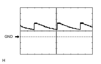
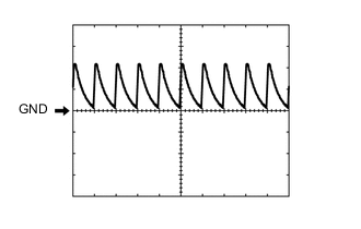
Using an oscilloscope, check waveform 1.
Waveform 1 (Reference) Item Content Terminal No. (Symbol) DH-7 (L2) - Body ground Tool Setting 5 V/DIV., 20 ms/DIV. Condition Ignition switch off, all doors closed and driver side door key cylinder neutral position -
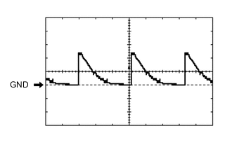
Using an oscilloscope, check waveform 2.
Waveform 2 (Reference) Item Content Terminal No. (Symbol) DH-7 (L2) - Body ground Tool Setting 5 V/DIV., 20 ms/DIV. Condition Ignition switch off, all doors closed and driver side door key cylinder neutral position -
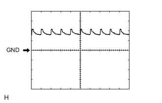
Using an oscilloscope, check waveform 3.
Waveform 3 (Reference) Item Content Terminal No. (Symbol) D79-25 (LSWD) - Body ground Tool Setting 5 V/DIV., 20 ms/DIV. Condition Ignition switch off, all doors closed and driver side door locked -
Using an oscilloscope, check waveform 4.
Waveform 4 (Reference) Item Content Terminal No. (Symbol) D79-25 (LSWD) - Body ground Tool Setting 5 V/DIV., 20 ms/DIV. Condition Ignition switch off, all doors closed and driver side door locked -
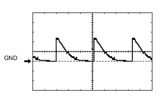
Using an oscilloscope, check waveform 5.
Waveform 5 (Reference) Item Content Terminal No. (Symbol) D79-10 (LSWP) - Body ground Tool Setting 5 V/DIV., 20 ms/DIV. Condition Ignition switch off, all doors closed and driver side door locked -
Using an oscilloscope, check waveform 6.
Waveform 6 (Reference) Item Content Terminal No. (Symbol) D79-10 (LSWP) - Body ground Tool Setting 5 V/DIV., 20 ms/DIV. Condition Ignition switch off, all doors closed and driver side door locked -
Using an oscilloscope, check waveform 7.
Waveform 7 (Reference) Item Content Terminal No. (Symbol) D81-10 (LSR) - Body ground Tool Setting 5 V/DIV., 20 ms/DIV. Condition Ignition switch off, all doors closed and rear door RH locked -
Using an oscilloscope, check waveform 8.
Waveform 8 (Reference) Item Content Terminal No. (Symbol) D81-10 (LSR) - Body ground Tool Setting 5 V/DIV., 20 ms/DIV. Condition Ignition switch off, all doors closed and rear door RH locked -
Using an oscilloscope, check waveform 9.
Waveform 9 (Reference) Item Content Terminal No. (Symbol) D79-12 (BDSU) - Body ground Tool Setting 5 V/DIV., 20 ms/DIV. Condition Ignition switch off, all doors closed and back door opener switch on -
Using an oscilloscope, check waveform 10.
Waveform 10 (Reference) Item Content Terminal No. (Symbol) D79-12 (BDSU) - Body ground Tool Setting 5 V/DIV., 20 ms/DIV. Condition Ignition switch off, all doors closed and back door opener switch on -
Using an oscilloscope, check waveform 11.
Waveform 11 (Reference) Item Content Terminal No. (Symbol) DH-6 (UL2) - Body ground Tool Setting 5 V/DIV., 20 ms/DIV. Condition Ignition switch off, all doors closed and driver side key cylinder neutral position -
Using an oscilloscope, check waveform 12.
Waveform 12 (Reference) Item Content Terminal No. (Symbol) DH-6 (UL2) - Body ground Tool Setting 5 V/DIV., 20 ms/DIV. Condition Ignition switch off, all doors closed and driver side key cylinder neutral position
-
-
CHECK DOUBLE LOCK DOOR CONTROL RELAY (w/ Double Locking System)

-
Disconnect the D107 relay connector.
-
Measure the voltage and resistance according to the value(s) in the table below.
Terminal No. (Symbol) Wiring Color Terminal Description Condition Specified Condition D107-14 (GND) - Body ground W-B - Body ground Ground Always Below 1 Ω D107-1 (+B) - Body ground B - Body ground Battery power supply Always 11 to 14 V D107-7 (CPUB) - Body ground W - Body ground Battery power supply Always 11 to 14 V If the result is not as specified, there may be a malfunction on the wire harness side.
-
Reconnect the D107 relay connector.
-
Measure the voltage according to the value(s) in the table below.
Terminal No. (Symbol) Wiring Color Terminal Description Condition Specified Condition D107-6 (DLPP) - Body ground L - Body ground Front door LH side double locking switch input Double lock not set 10 kΩ or higher D107-6 (DLPP) - Body ground L - Body ground Front door LH side double locking switch input Double lock set Below 1 Ω D107-5 (DLPD) - Body ground GR - Body ground Front door RH side double locking switch input Double lock not set 10 kΩ or higher D107-5 (DLPD) - Body ground GR - Body ground Front door RH side double locking switch input Double lock set Below 1 Ω D107-11 (DLPR) - Body ground L - Body ground Rear door RH side double locking switch input Double lock not set 10 kΩ or higher D107-11 (DLPR) - Body ground L - Body ground Rear door RH side double locking switch input Double lock set Below 1 Ω D107-12 (DLPL) - Body ground P - Body ground Rear door LH side double locking switch input Double lock not set 10 kΩ or higher D107-12 (DLPL) - Body ground P - Body ground Rear door LH side double locking switch input Double lock set Below 1 Ω D107-4 (ACTR) - Body ground G - Body ground All door double lock motor set off output Double lock set → not set Below 1 V → 11 to 14 V → Below 1 V D107-3 (ACTS) - Body ground BR - Body ground All door double lock motor set on output Double lock not set → set Below 1 V → 11 to 14 V → Below 1 V If the result is not as specified, the relay may have a malfunction.
-