CAN COMMUNICATION SYSTEM TERMINALS OF ECU
Tech Tips
Operating the ignition switch, any switches or any doors triggers related ECU and sensor communication with the CAN, which causes resistance variation.
-
DISCONNECT CABLE FROM NEGATIVE BATTERY TERMINAL
-
Disconnect the cable from the negative (-) battery terminal before measuring the resistances of the CAN main wire and CAN branch wire.
CAUTION:
Wait at least 90 seconds after disconnecting the cable from the negative (-) battery terminal to disable the SRS system.
Note
-
Before measuring the resistance, leave the vehicle for at least 1 minute and do not operate the ignition switch, any switches or any doors. If doors need to be opened in order to check connectors, open the doors and leave them open.
-
After turning the ignition switch off, waiting time may be required before disconnecting the cable from the battery terminal. Therefore, make sure to read the disconnecting the cable from the battery terminal notice before proceeding with work Click here.
-
When disconnecting the cable, some systems need to be initialized after the cable is reconnected Click here.
-
-
-
JUNCTION CONNECTOR
-
NO. 1 JUNCTION CONNECTOR
Tech Tips
Connectors that connect to the CAN junction connector can be distinguished by color of their CAN bus lines. When the connectors have been disconnected from the CAN junction connector, reconnecting the connectors to non-original positions on the CAN junction connector does not affect system performance. However, it is preferred to reconnect the connectors to their original positions to avoid negative effects on the wiring such as tension on the wiring harnesses, and to make future maintenance easier.
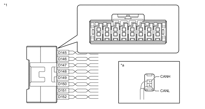
Text in Illustration *1 No. 1 Junction Connector - - *a Rear view of wire harness connector
(to No. 1 Junction Connector)
- - No. 1 Junction Connector Wiring Color Connect to D145-1 (CANH) Y ECM D145-2 (CANL) W D146-1 (CANH) R Brake actuator assembly (skid control ECU) D146-2 (CANL) W D147-1 (CANH) BR Spiral with sensor cable sub-assembly (steering angle sensor) D147-2 (CANL) W D148-1 (CANH) R Main body ECU (instrument panel junction block assembly) D148-2 (CANL) W D149-1 (CANH) L DLC3 D149-2 (CANL) W D150-1 (CANH) P Power steering ECU assembly D150-2 (CANL) W D151-1 (CANH) G Pre-crash safety city sensor* D151-2 (CANL) W D152-1 (CANH) B No. 2 junction connector D152-2 (CANL) W
-
*: w/ Pre-crash Safety System
-
-
NO. 2 JUNCTION CONNECTOR
Tech Tips
Connectors that connect to the CAN junction connector can be distinguished by color of their CAN bus lines. When the connectors have been disconnected from the CAN junction connector, reconnecting the connectors to non-original positions on the CAN junction connector does not affect system performance. However, it is preferred to reconnect the connectors to their original positions to avoid negative effects on the wiring such as tension on the wiring harnesses, and to make future maintenance easier.
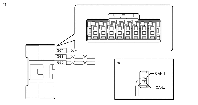
Text in Illustration *1 No. 2 Junction Connector - - *a Rear view of wire harness connector
(to No. 2 Junction Connector)
- - No. 2 Junction Connector Wiring Color Connect to G67-1 (CANH) P Parking brake with bracket actuator assembly (parking brake ECU) G67-2 (CANL) W G68-1 (CANH) G No. 3 junction connector G68-2 (CANL) W G69-1 (CANH) B No. 1 junction connector G69-2 (CANL) W -
NO. 3 JUNCTION CONNECTOR (w/ Entry and Start System)
Tech Tips
Connectors that connect to the CAN junction connector can be distinguished by color of their CAN bus lines. When the connectors have been disconnected from the CAN junction connector, reconnecting the connectors to non-original positions on the CAN junction connector does not affect system performance. However, it is preferred to reconnect the connectors to their original positions to avoid negative effects on the wiring such as tension on the wiring harnesses, and to make future maintenance easier.
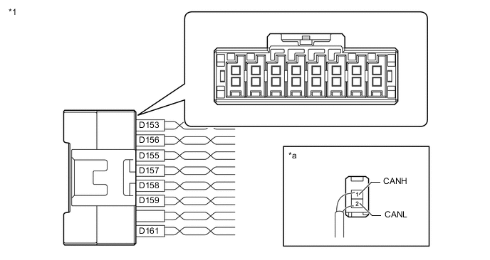
Text in Illustration *1 No. 3 Junction Connector - - *a Rear view of wire harness connector
(to No. 3 Junction Connector)
- - No. 3 Junction Connector Wiring Color Connect to D153-1 (CANH) SB Radio and display receiver assembly* D153-2 (CANL) W D155-1 (CANH) Y Center airbag sensor assembly D155-2 (CANL) W D156-1 (CANH) P Certification ECU (smart key ECU assembly) D156-2 (CANL) W D157-1 (CANH) R Power management control ECU D157-2 (CANL) W D158-1 (CANH) L Combination meter assembly D158-2 (CANL) W D159-1 (CANH) LG Yaw rate sensor D159-2 (CANL) W D161-1 (CANH) G No. 2 junction connector D161-2 (CANL) W
-
*: for Radio and Display Type
-
-
NO. 3 JUNCTION CONNECTOR (w/o Entry and Start System)
Tech Tips
Connectors that connect to the CAN junction connector can be distinguished by color of their CAN bus lines. When the connectors have been disconnected from the CAN junction connector, reconnecting the connectors to non-original positions on the CAN junction connector does not affect system performance. However, it is preferred to reconnect the connectors to their original positions to avoid negative effects on the wiring such as tension on the wiring harnesses, and to make future maintenance easier.
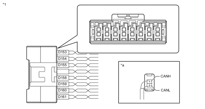
Text in Illustration *1 No. 3 Junction Connector - - *a Rear view of wire harness connector
(to No. 3 Junction Connector)
- - No. 3 Junction Connector Wiring Color Connect to D153-1 (CANH) SB Radio and display receiver assembly*1 D153-2 (CANL) W D154-1 (CANH) V Air conditioning amplifier assembly D154-2 (CANL) W D155-1 (CANH) Y Center airbag sensor assembly D155-2 (CANL) W D158-1 (CANH) L Combination meter assembly D158-2 (CANL) W D159-1 (CANH) LG Yaw rate sensor D159-2 (CANL) W D160-1 (CANH) P
-
Headlight swivel ECU assembly*2
-
Headlight leveling ECU assembly*3
D160-2 (CANL) W D161-1 (CANH) G No. 2 junction connector D161-2 (CANL) W
-
*1: for Radio and Display Type
-
*2: w/ Adaptive Front-lighting System
-
*3: w/o Adaptive Front-lighting System
-
-
NO. 4 JUNCTION CONNECTOR (w/ Entry and Start System)
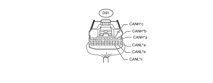
Text in Illustration *a for Air Conditioning Amplifier Assembly *b for Power Management Control ECU *c for ECM - - No. 4 Junction Connector Wiring Color Connect to D91-1 (CANH) V Air conditioning amplifier assembly D91-12 (CANL) W D91-2 (CANH) L Power management control ECU D91-13 (CANL) W D91-3 (CANH) R ECM D91-14 (CANL) W -
CAN JUNCTION CONNECTOR (w/ Entry and Start System)
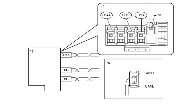
Text in Illustration *1 CAN Junction Connector *2 Junction Connector A Side *a Ground Terminal *b Rear view of wire harness connector
(to CAN Junction Connector)
CAN Junction Connector Wiring Color Connect to D93-1 (CANH) B Power management control ECU D93-2 (CANL) W D95-1 (CANH) P
-
Headlight swivel ECU assembly*1
-
Headlight leveling ECU assembly*2
D95-2 (CANL) W D144-1 (CANH) V Air conditioning amplifier assembly*3 D144-2 (CANL) W
-
*1: w/ Adaptive Front-lighting System
-
*2: w/o Adaptive Front-lighting System
-
*3: except 3ZR-FE
-
-
-
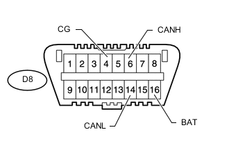
CHECK DLC3
-
Disconnect the cable from the negative (-) battery terminal before measuring the resistances of the CAN main wire and CAN branch wire.
Note
-
After turning the ignition switch off, waiting time may be required before disconnecting the cable from the battery terminal. Therefore, make sure to read the disconnecting the cable from the battery terminal notice before proceeding with work Click here.
-
When disconnecting the cable, some systems need to be initialized after the cable is reconnected Click here.
-
-
Measure the resistance according to the value(s) in the table below.
Terminal No. (Symbol) Wiring Color Switch Condition Specified Condition D8-6 (CANH) - D8-14 (CANL) L - W Ignition switch off 54 to 69 Ω D8-6 (CANH) - D8-4 (CG) L - W-B Ignition switch off 200 Ω or higher D8-14 (CANL) - D8-4 (CG) W - W-B Ignition switch off 200 Ω or higher D8-6 (CANH) - D8-16 (BAT) L - G Ignition switch off 6 kΩ or higher D8-14 (CANL) - D8-16 (BAT) W - G Ignition switch off 6 kΩ or higher
-
-
CHECK ECM (for 3ZR-FE)
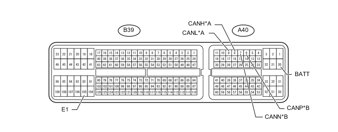
Text in Illustration *A V1 Bus *B Power Management Bus
-
Disconnect the ECM connectors.
-
Measure the resistance according to the value(s) in the table below.
for V1 Bus Terminal No. (Symbol) Wiring Color Switch Condition Specified Condition A40-8 (CANH) - A40-9 (CANL) Y - W Ignition switch off 108 to 132 Ω A40-8 (CANH) - B39-105 (E1) Y - BR Ignition switch off 200 Ω or higher A40-9 (CANL) - B39-105 (E1) W - BR Ignition switch off 200 Ω or higher A40-8 (CANH) - A40-20 (BATT) Y - P Ignition switch off 6 kΩ or higher A40-9 (CANL) - A40-20 (BATT) W - P Ignition switch off 6 kΩ or higher for Power Management Bus Terminal No. (Symbol) Wiring Color Switch Condition Specified Condition A40-6 (CANP) - A40-7 (CANN) R - W Ignition switch off 108 to 132 Ω A40-6 (CANP) - B39-105 (E1) R - BR Ignition switch off 200 Ω or higher A40-7 (CANN) - B39-105 (E1) W - BR Ignition switch off 200 Ω or higher A40-6 (CANP) - A40-20 (BATT) R - P Ignition switch off 6 kΩ or higher A40-7 (CANN) - A40-20 (BATT) W - P Ignition switch off 6 kΩ or higher
-
-
CHECK ECM (except 3ZR-FE)
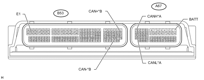
Text in Illustration *A V1 Bus *B Powertrain Bus
-
Disconnect the ECM connectors.
-
Measure the resistance according to the value(s) in the table below.
for V1 Bus Terminal No. (Symbol) Wiring Color Switch Condition Specified Condition A67-13 (CANH) - A67-26 (CANL) Y - W Ignition switch off 108 to 132 Ω A67-13 (CANH) - B53-59 (E1) Y - BR Ignition switch off 200 Ω or higher A67-26 (CANL) - B53-59 (E1) W - BR Ignition switch off 200 Ω or higher A67-13 (CANH) - A67-1 (BATT) Y - P Ignition switch off 6 kΩ or higher A67-26 (CANL) - A67-1 (BATT) W - P Ignition switch off 6 kΩ or higher for Powertrain Bus Terminal No. (Symbol) Wiring Color Switch Condition Specified Condition B53-31 (CAN+) - B53-32 (CAN-) Y - W Ignition switch off 108 to 132 Ω B53-31 (CAN+) - B53-59 (E1) Y - BR Ignition switch off 200 Ω or higher B53-32 (CAN-) - B53-59 (E1) W - BR Ignition switch off 200 Ω or higher B53-31 (CAN+) - A67-1 (BATT) Y - P Ignition switch off 6 kΩ or higher B53-32 (CAN-) - A67-1 (BATT) W - P Ignition switch off 6 kΩ or higher
-
-
CHECK POWER MANAGEMENT CONTROL ECU (w/ Entry and Start System)
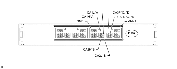
Text in Illustration *A V1 Bus *B V2 Bus (for 3ZR-FE) *C V2 Bus (except 3ZR-FE) *D Power Management Bus (for 3ZR-FE)
-
Disconnect the power management control ECU connector.
-
Measure the resistance according to the value(s) in the table below.
for V1 Bus Terminal No. (Symbol) Wiring Color Switch Condition Specified Condition D109-14 (CA1H) - D109-13 (CA1L) R - W Ignition switch off 54 to 69 Ω D109-14 (CA1H) - D109-6 (GND) R - W-B Ignition switch off 200 Ω or higher D109-13 (CA1L) - D109-6 (GND) W - W-B Ignition switch off 200 Ω or higher D109-14 (CA1H) - D109-2 (AM21) R - W Ignition switch off 6 kΩ or higher D109-13 (CA1L) - D109-2 (AM21) W - W Ignition switch off 6 kΩ or higher for V2 Bus, 3ZR-FE Terminal No. (Symbol) Wiring Color Switch Condition Specified Condition D109-26 (CA2H) - D109-25 (CA2L) B - W Ignition switch off 108 to 132 Ω D109-26 (CA2H) - D109-6 (GND) B - W-B Ignition switch off 200 Ω or higher D109-25 (CA2L) - D109-6 (GND) W - W-B Ignition switch off 200 Ω or higher D109-26 (CA2H) - D109-2 (AM21) B - W Ignition switch off 6 kΩ or higher D109-25 (CA2L) - D109-2 (AM21) W - W Ignition switch off 6 kΩ or higher for V2 Bus, except 3ZR-FE Terminal No. (Symbol) Wiring Color Switch Condition Specified Condition D109-12 (CA3P) - D109-11 (CA3N) B - W Ignition switch off 108 to 132 Ω D109-12 (CA3P) - D109-6 (GND) B - W-B Ignition switch off 200 Ω or higher D109-11 (CA3N) - D109-6 (GND) W - W-B Ignition switch off 200 Ω or higher D109-12 (CA3P) - D109-2 (AM21) B - W Ignition switch off 6 kΩ or higher D109-11 (CA3N) - D109-2 (AM21) W - W Ignition switch off 6 kΩ or higher for Power Management Bus, 3ZR-FE Terminal No. (Symbol) Wiring Color Switch Condition Specified Condition D109-12 (CA3P) - D109-11 (CA3N) L - W Ignition switch off 108 to 132 Ω D109-12 (CA3P) - D109-6 (GND) L - W-B Ignition switch off 200 Ω or higher D109-11 (CA3N) - D109-6 (GND) W - W-B Ignition switch off 200 Ω or higher D109-12 (CA3P) - D109-2 (AM21) L - W Ignition switch off 6 kΩ or higher D109-11 (CA3N) - D109-2 (AM21) W - W Ignition switch off 6 kΩ or higher
-
-
CHECK POWER MANAGEMENT CONTROL ECU (w/o Entry and Start System)

-
Disconnect the power management control ECU connector.
-
Measure the resistance according to the value(s) in the table below.
Terminal No. (Symbol) Wiring Color Switch Condition Specified Condition D104-4 (CA3P) - D104-3 (CA3N) R - W Ignition switch off 108 to 132 Ω D104-4 (CA3P) - D104-12 (GND) R - W-B Ignition switch off 200 Ω or higher D104-3 (CA3N) - D104-12 (GND) W - W-B Ignition switch off 200 Ω or higher D104-4 (CA3P) - D104-8 (AM21) R - W Ignition switch off 6 kΩ or higher D104-3 (CA3N) - D104-8 (AM21) W - W Ignition switch off 6 kΩ or higher
-
-
CHECK MAIN BODY ECU (INSTRUMENT PANEL JUNCTION BLOCK ASSEMBLY)
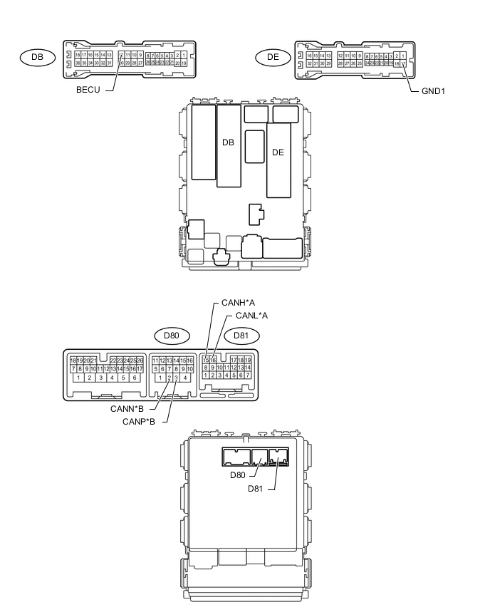
Text in Illustration *A V1 Bus *B MS Bus
-
Disconnect the main body ECU (instrument panel junction block assembly) connectors.
-
Measure the resistance according to the value(s) in the table below.
for V1 Bus Terminal No. (Symbol) Wiring Color Switch Condition Specified Condition D81-15 (CANH) - D81-16 (CANL) R - W Ignition switch off 54 to 69 Ω D81-15 (CANH) - DE-17 (GND1) R - W-B Ignition switch off 200 Ω or higher D81-16 (CANL) - DE-17 (GND1) W - W-B Ignition switch off 200 Ω or higher D81-15 (CANH) - DB-12 (BECU) R - W Ignition switch off 6 kΩ or higher D81-16 (CANL) - DB-12 (BECU) W - W Ignition switch off 6 kΩ or higher for MS Bus Terminal No. (Symbol) Wiring Color Switch Condition Specified Condition D80-3 (CANP) - D80-2 (CANN) SB - W Ignition switch off 108 to 132 Ω D80-3 (CANP) - DE-17 (GND1) SB - W-B Ignition switch off 200 Ω or higher D80-2 (CANN) - DE-17 (GND1) W - W-B Ignition switch off 200 Ω or higher D80-3 (CANP) - DB-12 (BECU) SB - W Ignition switch off 6 kΩ or higher D80-2 (CANN) - DB-12 (BECU) W - W Ignition switch off 6 kΩ or higher
-
-
CHECK BRAKE ACTUATOR ASSEMBLY (SKID CONTROL ECU)
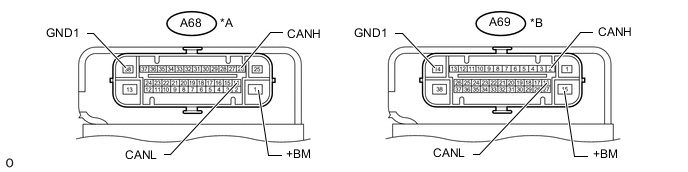
Text in Illustration *A for CVT *B except CVT
-
Disconnect the brake actuator assembly (skid control ECU) connector.
-
Measure the resistance according to the value(s) in the table below.
for CVT Terminal No. (Symbol) Wiring Color Switch Condition Specified Condition A68-26 (CANH) - A68-14 (CANL) R - W Ignition switch off 54 to 69 Ω A68-26 (CANH) - A68-38 (GND1) R - W-B Ignition switch off 200 Ω or higher A68-14 (CANL) - A68-38 (GND1) W - W-B Ignition switch off 200 Ω or higher A68-26 (CANH) - A68-1 (+BM) R - L Ignition switch off 6 kΩ or higher A68-14 (CANL) - A68-1 (+BM) W - L Ignition switch off 6 kΩ or higher except CVT Terminal No. (Symbol) Wiring Color Switch Condition Specified Condition A69-2 (CANH) - A69-16 (CANL) R - W Ignition switch off 54 to 69 Ω A69-2 (CANH) - A69-14 (GND1) R - W-B Ignition switch off 200 Ω or higher A69-16 (CANL) - A69-14 (GND1) W - W-B Ignition switch off 200 Ω or higher A69-2 (CANH) - A69-15 (+BM) R - L Ignition switch off 6 kΩ or higher A69-16 (CANL) - A69-15 (+BM) W - L Ignition switch off 6 kΩ or higher
-
-
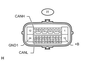
CHECK PARKING BRAKE WITH BRACKET ACTUATOR ASSEMBLY (PARKING BRAKE ECU)
-
Disconnect the parking brake with bracket actuator assembly (parking brake ECU) connector.
-
Measure the resistance according to the value(s) in the table below.
Terminal No. (Symbol) Wiring Color Switch Condition Specified Condition I1-11 (CANH) - I1-23 (CANL) P - W Ignition switch off 54 to 69 Ω I1-11 (CANH) - I1-24 (GND1) P - W-B Ignition switch off 200 Ω or higher I1-23 (CANL) - I1-24 (GND1) W - W-B Ignition switch off 200 Ω or higher I1-11 (CANH) - I1-13 (+B) P - B Ignition switch off 6 kΩ or higher I1-23 (CANL) - I1-13 (+B) W - B Ignition switch off 6 kΩ or higher
-
-
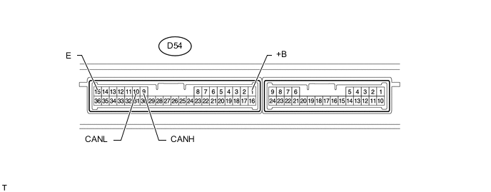
CHECK CERTIFICATION ECU (SMART KEY ECU ASSEMBLY) (w/ Entry and Start System)
-
Disconnect the certification ECU (smart key ECU assembly) connector.
-
Measure the resistance according to the value(s) in the table below.
Terminal No. (Symbol) Wiring Color Switch Condition Specified Condition D54-9 (CANH) - D54-10 (CANL) P - W Ignition switch off 54 to 69 Ω D54-9 (CANH) - D54-15 (E) P - W-B Ignition switch off 200 Ω or higher D54-10 (CANL) - D54-15 (E) W - W-B Ignition switch off 200 Ω or higher D54-9 (CANH) - D54-1 (+B) P - R Ignition switch off 6 kΩ or higher D54-10 (CANL) - D54-1 (+B) W - R Ignition switch off 6 kΩ or higher
-
-
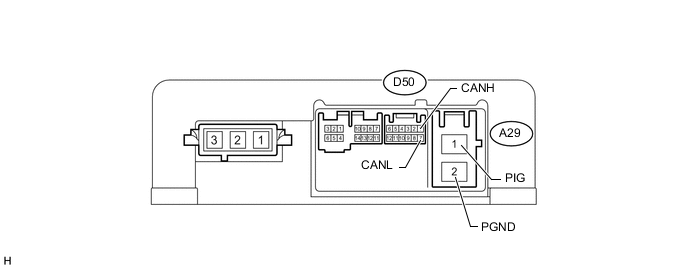
CHECK POWER STEERING ECU ASSEMBLY
-
Disconnect the power steering ECU assembly connectors.
-
Measure the resistance according to the value(s) in the table below.
Terminal No. (Symbol) Wiring Color Switch Condition Specified Condition D50-1 (CANH) - D50-7 (CANL) P - W Ignition switch off 54 to 69 Ω D50-1 (CANH) - A29-2 (PGND) P - W Ignition switch off 200 Ω or higher D50-7 (CANL) - A29-2 (PGND) W - W Ignition switch off 200 Ω or higher D50-1 (CANH) - A29-1 (PIG) P - B Ignition switch off 6 kΩ or higher D50-7 (CANL) - A29-1 (PIG) W - B Ignition switch off 6 kΩ or higher
-
-
CHECK AIR CONDITIONING AMPLIFIER ASSEMBLY
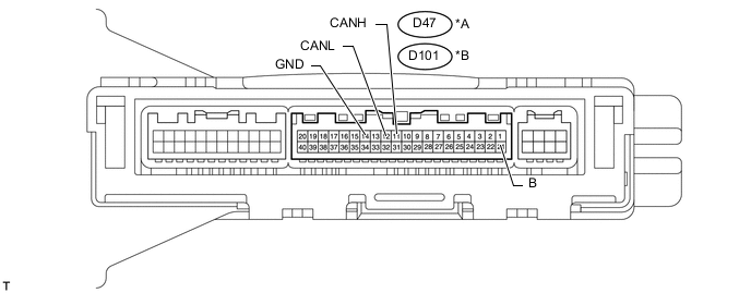
Text in Illustration *A for Automatic Air Conditioning System *B for Manual Air Conditioning System and w/o Air Conditioning System
-
Disconnect the air conditioning amplifier assembly connector.
-
Measure the resistance according to the value(s) in the table below.
for Automatic Air Conditioning System Terminal No. (Symbol) Wiring Color Switch Condition Specified Condition D47-11 (CANH) - D47-12 (CANL) V - W Ignition switch off 54 to 69 Ω D47-11 (CANH) - D47-14 (GND) V - W-B Ignition switch off 200 Ω or higher D47-12 (CANL) - D47-14 (GND) W - W-B Ignition switch off 200 Ω or higher D47-11 (CANH) - D47-21 (B) V - R Ignition switch off 6 kΩ or higher D47-12 (CANL) - D47-21 (B) W - R Ignition switch off 6 kΩ or higher for Manual Air Conditioning System and w/o Air Conditioning System Terminal No. (Symbol) Wiring Color Switch Condition Specified Condition D101-11 (CANH) - D101-12 (CANL) V - W Ignition switch off 54 to 69 Ω D101-11 (CANH) - D101-14 (GND) V - W-B Ignition switch off 200 Ω or higher D101-12 (CANL) - D101-14 (GND) W - W-B Ignition switch off 200 Ω or higher D101-11 (CANH) - D101-21 (B) V - R Ignition switch off 6 kΩ or higher D101-12 (CANL) - D101-21 (B) W - R Ignition switch off 6 kΩ or higher
-
-
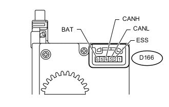
CHECK SPIRAL WITH SENSOR CABLE SUB-ASSEMBLY (STEERING ANGLE SENSOR)
-
Disconnect the spiral with sensor cable sub-assembly (steering angle sensor) connector.
-
Measure the resistance according to the value(s) in the table below.
Terminal No. (Symbol) Wiring Color Switch Condition Specified Condition D166-4 (CANH) - D166-3 (CANL) BR - W Ignition switch off 54 to 69 Ω D166-4 (CANH) - D166-2 (ESS) BR - BR Ignition switch off 200 Ω or higher D166-3 (CANL) - D166-2 (ESS) W - BR Ignition switch off 200 Ω or higher D166-4 (CANH) - D166-6 (BAT) BR - W Ignition switch off 6 kΩ or higher D166-3 (CANL) - D166-6 (BAT) W - W Ignition switch off 6 kΩ or higher
-
-
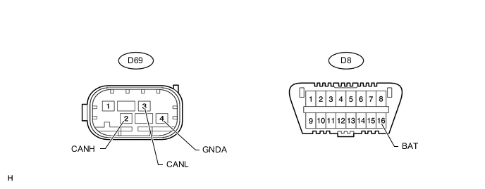
CHECK YAW RATE SENSOR
-
Disconnect the yaw rate sensor connector.
-
Measure the resistance according to the value(s) in the table below.
Terminal No. (Symbol) Wiring Color Switch Condition Specified Condition D69-2 (CANH) - D69-3 (CANL) LG - W Ignition switch off 54 to 69 Ω D69-2 (CANH) - D69-4 (GNDA) LG - BR Ignition switch off 200 Ω or higher D69-3 (CANL) - D69-4 (GNDA) W - BR Ignition switch off 200 Ω or higher D69-2 (CANH) - D8-16 (BAT) LG - G Ignition switch off 6 kΩ or higher D69-3 (CANL) - D8-16 (BAT) W - G Ignition switch off 6 kΩ or higher
-
-
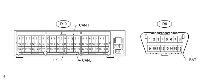
CHECK CENTER AIRBAG SENSOR ASSEMBLY
-
Disconnect the center airbag sensor assembly connector.
-
Measure the resistance according to the value(s) in the table below.
Terminal No. (Symbol) Wiring Color Switch Condition Specified Condition D10-13 (CANH) - D10-22 (CANL) Y - W Ignition switch off 54 to 69 Ω D10-13 (CANH) - D10-25 (E1) Y - W-B Ignition switch off 200 Ω or higher D10-22 (CANL) - D10-25 (E1) W - W-B Ignition switch off 200 Ω or higher D10-13 (CANH) - D8-16 (BAT) Y - G Ignition switch off 6 kΩ or higher D10-22 (CANL) - D8-16 (BAT) W - G Ignition switch off 6 kΩ or higher
-
-
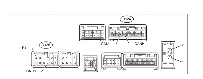
CHECK RADIO AND DISPLAY RECEIVER ASSEMBLY (for Radio and Display Type)
-
Disconnect the radio and display receiver assembly connectors.
-
Measure the resistance according to the value(s) in the table below.
Terminal No. (Symbol) Wiring Color Switch Condition Specified Condition D124-9 (CANH) - D124-10 (CANL) SB - W Ignition switch off 54 to 69 Ω D124-9 (CANH) - D125-7 (GND1) SB - BR Ignition switch off 200 Ω or higher D124-10 (CANL) - D125-7 (GND1) W - BR Ignition switch off 200 Ω or higher D124-9 (CANH) - D125-4 (+B1) SB - SB Ignition switch off 6 kΩ or higher D124-10 (CANL) - D125-4 (+B1) W - SB Ignition switch off 6 kΩ or higher
-
-
CHECK COMBINATION METER ASSEMBLY

-
Disconnect the D66 combination meter assembly connector.
-
Measure the resistance according to the value(s) in the table below.
Terminal No. (Symbol) Wiring Color Switch Condition Specified Condition D66-32 (CANH) - D66-31 (CANL) L - W Ignition switch off 108 to 132 Ω D66-32 (CANH) - D66-21 (ET) L - W-B Ignition switch off 200 Ω or higher D66-31 (CANL) - D66-21 (ET) W - W-B Ignition switch off 200 Ω or higher D66-32 (CANH) - D66-40 (B) L - W Ignition switch off 6 kΩ or higher D66-31 (CANL) - D66-40 (B) W - W Ignition switch off 6 kΩ or higher
-
-
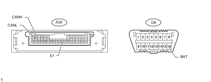
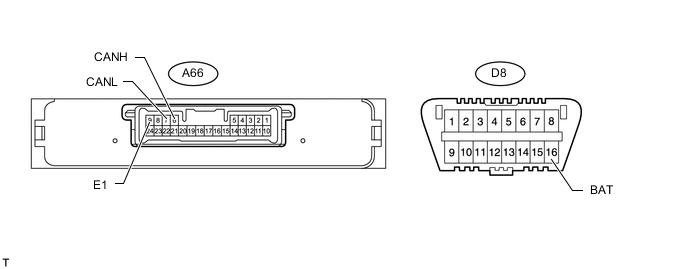
CHECK HEADLIGHT SWIVEL ECU ASSEMBLY (w/ Adaptive Front-lighting System) or HEADLIGHT LEVELING ECU ASSEMBLY (w/o Adaptive Front-lighting System)
-
w/ Adaptive Front-lighting System
-
Disconnect the headlight swivel ECU assembly connector.
-
Measure the resistance according to the value(s) in the table below.
Terminal No. (Symbol) Wiring Color Switch Condition Specified Condition A38-12 (CANH) - A38-13 (CANL) P - W Ignition switch off 54 to 69 Ω A38-12 (CANH) - A38-22 (E1) P - W-B Ignition switch off 200 Ω or higher A38-13 (CANL) - A38-22 (E1) W - W-B Ignition switch off 200 Ω or higher A38-12 (CANH) - D8-16 (BAT) P - G Ignition switch off 6 kΩ or higher A38-13 (CANL) - D8-16 (BAT) W - G Ignition switch off 6 kΩ or higher
-
-
w/o Adaptive Front-lighting System
-
Disconnect the headlight leveling ECU assembly connector.
-
Measure the resistance according to the value(s) in the table below.
Terminal No. (Symbol) Wiring Color Switch Condition Specified Condition A66-6 (CANH) - A66-7 (CANL) P - W Ignition switch off 54 to 69 Ω A66-6 (CANH) - A66-9 (E1) P - W-B Ignition switch off 200 Ω or higher A66-7 (CANL) - A66-9 (E1) W - W-B Ignition switch off 200 Ω or higher A66-6 (CANH) - D8-16 (BAT) P - G Ignition switch off 6 kΩ or higher A66-7 (CANL) - D8-16 (BAT) W - G Ignition switch off 6 kΩ or higher
-
-
-
CHECK POSITION CONTROL ECU ASSEMBLY (w/ Seat Position Memory System)
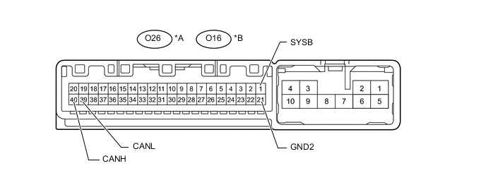
Text in Illustration *A for LHD *B for RHD
-
Disconnect the position control ECU assembly connector.
-
Measure the resistance according to the value(s) in the table below.
for LHD Terminal No. (Symbol) Wiring Color Switch Condition Specified Condition O26-40 (CANH) - O26-39 (CANL) SB - W Ignition switch off 108 to 132 Ω O26-40 (CANH) - O26-21 (GND2) SB - BR Ignition switch off 200 Ω or higher O26-39 (CANL) - O26-21 (GND2) W - BR Ignition switch off 200 Ω or higher O26-40 (CANH) - O26-1 (SYSB) SB - R Ignition switch off 6 kΩ or higher O26-39 (CANL) - O26-1 (SYSB) W - R Ignition switch off 6 kΩ or higher for RHD Terminal No. (Symbol) Wiring Color Switch Condition Specified Condition O16-40 (CANH) - O16-39 (CANL) SB - W Ignition switch off 108 to 132 Ω O16-40 (CANH) - O16-21 (GND2) SB - BR Ignition switch off 200 Ω or higher O16-39 (CANL) - O16-21 (GND2) W - BR Ignition switch off 200 Ω or higher O16-40 (CANH) - O16-1 (SYSB) SB - R Ignition switch off 6 kΩ or higher O16-39 (CANL) - O16-1 (SYSB) W - R Ignition switch off 6 kΩ or higher
-
-
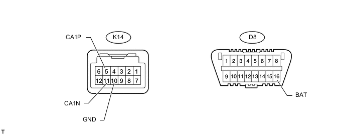
CHECK PRE-CRASH SAFETY CITY SENSOR (w/ Pre-crash Safety System)
-
Disconnect the pre-crash safety city sensor connector.
-
Measure the resistance according to the value(s) in the table below.
Terminal No. (Symbol) Wiring Color Switch Condition Specified Condition K14-5 (CA1P) - K14-11 (CA1N) G - W Ignition switch off 54 to 69 Ω K14-5 (CA1P) - K14-10 (GND) G - W-B Ignition switch off 200 Ω or higher K14-11 (CA1N) - K14-10 (GND) W - W-B Ignition switch off 200 Ω or higher K14-5 (CA1P) - D8-16 (BAT) G - G Ignition switch off 6 kΩ or higher K14-11 (CA1N) - D8-16 (BAT) W - G Ignition switch off 6 kΩ or higher
-
-
CHECK CONTINUOUSLY VARIABLE VALVE LIFT CONTROLLER ASSEMBLY (except 3ZR-FE)

-
Disconnect the continuously variable valve lift controller assembly connector.
-
Measure the resistance according to the value(s) in the table below.
Terminal No. (Symbol) Wiring Color Switch Condition Specified Condition B37-4 (CAN+) - B37-2 (CAN-) Y - W Ignition switch off 108 to 132 Ω B37-4 (CAN+) - D8-4 (CG) Y - W-B Ignition switch off 200 Ω or higher B37-2 (CAN-) - D8-4 (CG) W - W-B Ignition switch off 200 Ω or higher B37-4 (CAN+) - B37-1 (+B) Y - B Ignition switch off 6 kΩ or higher B37-2 (CAN-) - B37-1 (+B) W - B Ignition switch off 6 kΩ or higher
-