CHARGING SYSTEM, Diagnostic DTC:P1550, P1551, P1552
| DTC Code | DTC Name |
|---|---|
| P1550 | Battery Current Sensor Circuit |
| P1551 | Battery Current Sensor Circuit Low |
| P1552 | Battery Current Sensor Circuit High |
DESCRIPTION
The battery current sensor assembly detects the battery charge and discharge current amount. The battery current sensor assembly changes this information into a voltage signal and outputs it to the ECM. Based on this signal, the ECM sends power generation voltage commands to the generator.
| DTC Code | DTC Detection Condition | Trouble Area |
|---|---|---|
| P1550 | When the ignition switch is ON, the difference between the maximum and minimum current values is below 1 A for 10 seconds or more (1 trip detection logic). |
|
| P1551 | When the ignition switch is ON, the battery current sensor output is below 0.2 V for 0.5 seconds or more (1 trip detection logic). |
|
| P1552 | When the ignition switch is ON, the battery current sensor output is higher than 4.8 V for 0.5 seconds or more (1 trip detection logic). |
|
WIRING DIAGRAM
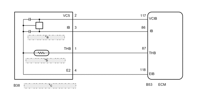
| *a | Battery Current Sensor |
| *b | Battery Temperature Sensor |
| *c | Battery Current Sensor Assembly |
PROCEDURE
-
CHECK FOR DTC
-
Connect the GTS to the DLC3.
-
Start the engine.
-
Turn the GTS on.
-
Check for DTCs Click here.
Result Result Proceed to DTC P1550, P1551 or P1552 is output. A DTCs other than P1550, P1551 and P1552 are output. B
B 
GO TO DIAGNOSTIC TROUBLE CODE CHART Click here
A 
-
-
READ VALUE USING GTS (BATTERY CURRENT)
-
Connect the GTS to the DLC3.
-
Turn the ignition switch to ON and turn off all electrical devices (headlights, blower motor, wiper, rear defogger, etc.).
-
Turn the GTS on.
-
Enter the following menus: Powertrain / Engine and ECT / Data List.
-
Check the values by referring to the table below.
Charging Control Tester Display Measurement Item/Range Normal Condition Diagnostic Note Battery Current Battery current / -125.0 to 124.9 A Changes in response to generator power generation amount after engine warmed up while vehicle driven - Result Result Proceed to Current value displayed on GTS is fixed at 0 A and does not change, or only changes by 1 A or less between -125 and 124.9 A. A Current value displayed on GTS changes between -20 and 0 A. B
B
USE SIMULATION METHOD TO CHECK Click here
A
-
-
INSPECT BATTERY CURRENT SENSOR ASSEMBLY
-
Inspect the battery current sensor assembly Click here.
NG
REPLACE BATTERY CURRENT SENSOR ASSEMBLY Click here
OK
-
-
CHECK HARNESS AND CONNECTOR (BATTERY CURRENT SENSOR ASSEMBLY - ECM)
-
Disconnect the B53ECM connector.
-
Disconnect the B38 battery current sensor assembly connector.
-
Measure the resistance according to the value(s) in the table below.
Standard Resistance Tester Connection Condition Specified Condition B53-117 (VCIB) - B38-2 (VC5) Always Below 1 Ω B53-118 (EIB) - B38-4 (E2) B53-86 (IB) - B38-3 (IB) B53-117 (VCIB) or B38-2 (VC5) - Body ground Always 10 kΩ or higher B53-118 (EIB) or B38-4 (E2) - Body ground B53-86 (IB) or B38-3 (IB) - Body ground
OK
REPLACE ECM Click here
NG
REPAIR OR REPLACE HARNESS OR CONNECTOR
-