FRONT SEAT OUTER BELT ASSEMBLY INSTALLATION

CAUTION / NOTICE / HINT
Tech Tips
-
Use the same procedure for the RH and LH sides.
-
The procedure listed below is for the LH side.
-
A bolt without a torque specification is shown in the standard bolt chart Click here.
PROCEDURE
-
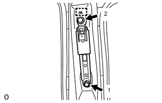
INSTALL FRONT SHOULDER BELT ANCHOR ADJUSTER ASSEMBLY
-
Attach the guide and install the front shoulder belt anchor adjuster assembly with the 2 bolts.
Tech Tips
Tighten the 2 bolts in the order shown in the illustration.
- Torque:
- 42 N*m { 428 kgf*cm, 31 ft.*lbf }
-
-
INSTALL FRONT SEAT OUTER BELT ASSEMBLY LH
-
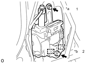
Text in Illustration *a Bolt A *b Bolt B Attach the 2 guides and temporarily install the front seat outer belt assembly LH with the 2 bolts.
-
Tighten the 2 bolts in the order shown in the illustration.
- Torque:
- for bolt A
- 12.5 N*m { 127 kgf*cm, 9 in.*lbf }
- for bolt B
- 42 N*m { 428 kgf*cm, 31 ft.*lbf }
-
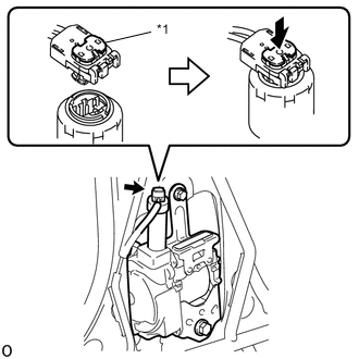
Text in Illustration *1 Locking Button Connect the pretensioner connector and lock the locking button as shown in the illustration.
Note
Securely lock the locking button.
-
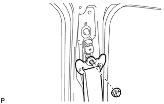
Connect the shoulder anchor of the front seat outer belt assembly LH with the nut.
- Torque:
- 42 N*m { 428 kgf*cm, 31 ft.*lbf }
-
-
INSTALL CENTER PILLAR GARNISH LH
-
INSTALL LAP BELT OUTER ANCHOR COVER
-
INSTALL LOWER CENTER PILLAR GARNISH LH
-
INSTALL REAR DOOR SCUFF PLATE LH
-
INSTALL FRONT DOOR SCUFF PLATE LH
-
CONNECT CABLE TO NEGATIVE BATTERY TERMINAL
Note
When disconnecting the cable, some systems need to be initialized after the cable is reconnected Click here.