AUDIO AND VISUAL SYSTEM(for Radio Receiver Type) Microphone Circuit between Microphone and Radio Receiver
DESCRIPTION
-
The radio receiver assembly and map light assembly (telephone microphone assembly) are connected to each other using the microphone connection detection signal lines.
-
Using this circuit, the radio receiver assembly sends power to the map light assembly (telephone microphone assembly), and the map light assembly (telephone microphone assembly) sends microphone signals to the radio receiver assembly.
WIRING DIAGRAM
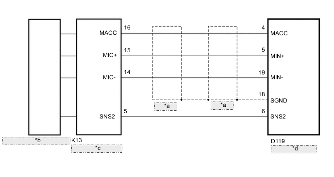
| *a | Shielded |
| *b | Telephone Microphone Assembly |
| *c | Map Light Assembly |
| *d | Radio Receiver Assembly |
PROCEDURE
-
CHECK HARNESS AND CONNECTOR (RADIO RECEIVER ASSEMBLY - MAP LIGHT ASSEMBLY)
-
Disconnect the D119 radio receiver assembly connector.
-
Disconnect the K13 map light assembly connector.
-
Measure the resistance according to the value(s) in the table below.
Standard Resistance Tester Connection Condition Specified Condition D119-4 (MACC) - K13-16 (MACC) Always Below 1 Ω D119-5 (MIN+) - K13-15 (MIC+) Always Below 1 Ω D119-19 (MIN-) - K13-14 (MIC-) Always Below 1 Ω D119-6 (SNS2) - K13-5 (SNS2) Always Below 1 Ω D119-4 (MACC) - Body ground Always 10 kΩ or higher D119-5 (MIN+) - Body ground Always 10 kΩ or higher D119-19 (MIN-) - Body ground Always 10 kΩ or higher D119-6 (SNS2) - Body ground Always 10 kΩ or higher D119-18 (SGND) - Body ground Always 10 kΩ or higher
NG 
REPAIR OR REPLACE HARNESS OR CONNECTOR
OK 
-
-
CHECK RADIO RECEIVER ASSEMBLY
-
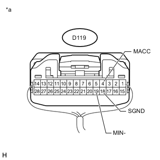
Text in Illustration *a Component with harness connected
(Radio Receiver Assembly)
Remove the radio receiver assembly with the connector still connected Click here.
-
Measure the resistance according to the value(s) in the table below.
Standard Resistance Tester Connection Condition Specified Condition D119-18 (SGND) - Body ground Always Below 1 Ω D119-19 (MIN-) - Body ground Always Below 1 Ω -
Measure the voltage according to the value(s) in the table below.
Standard Voltage Tester Connection Switch Condition Specified Condition D119-4 (MACC) - Body ground Ignition switch ACC 4 to 6 V
NG
REPLACE RADIO RECEIVER ASSEMBLY Click here
OK
-
-
CHECK TELEPHONE MICROPHONE ASSEMBLY
-
Replace the telephone microphone assembly Click here.
-
Check if the same problem occurs again.
OK Malfunction disappears.
OK
END (TELEPHONE MICROPHONE ASSEMBLY IS DEFECTIVE)
NG
REPLACE MAP LIGHT ASSEMBLY Click here
-