STEERING WHEEL INSPECTION

CAUTION / NOTICE / HINT
CAUTION:
The vehicle is equipped with an SRS which includes components such as airbags. Before servicing (including removal or installation of parts), be sure to read the precautionary notice for the SRS Click here.
PROCEDURE
-
INSPECT STEERING PAD SWITCH ASSEMBLY
-
Remove the steering pad switch assembly Click here.
-
Measure the resistance according to the value(s) in the table below.

Standard Resistance Tester Connection Switch Condition Specified Condition 10 (AU1) - 8 (EAU) No switch is pushed 95 to 105 kΩ Seek+ switch is pushed Below 2.5 Ω Seek- switch is pushed 312 to 345 Ω Volume+ switch is pushed 950 to 1050 Ω Volume- switch is pushed 2954 to 3265 Ω 9 (AU2) - 8 (EAU) No switch is pushed 95 to 105 kΩ MODE switch is pushed Below 2.5 Ω On Hook switch is pushed 312 to 345 Ω Off Hook switch is pushed 950 to 1050 Ω 7 (DISP) - 8 (EAU) DISP switch is pushed Below 2.5 Ω 1 (HO) - Horn wire Always Below 1 Ω
-
-
INSPECT TRANSMISSION SHIFT SWITCH ASSEMBLY (LH (-) AND RH (+))
-
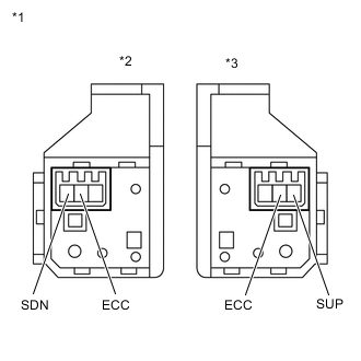
Text in Illustration *1 Component without wire harness connected
(Transmission Shift Switch Assembly)
*2 for LH *3 for RH Measure the resistance according to the value(s) in the table below.
Standard Resistance for LH Tester Connection Condition Specified Condition SDN - ECC "-" shift paddle operated and held (down-shift) Below 2.5 Ω SDN - ECC "-" shift paddle not operated (down-shift) 1 MΩ or higher for RH Tester Connection Condition Specified Condition SUP - ECC "+" shift paddle operated and held (up-shift) Below 2.5 Ω SUP - ECC "+" shift paddle not operated (up-shift) 1 MΩ or higher
-