POWER TILT AND POWER TELESCOPIC STEERING COLUMN SYSTEM IG Power Source Circuit
DESCRIPTION
When the engine switch is turned on (IG), the IG power source circuit supplies positive (+) voltage to the multiplex tilt and telescopic ECU.
The multiplex tilt and telescopic ECU also receives engine switch signals via this circuit.
WIRING DIAGRAM
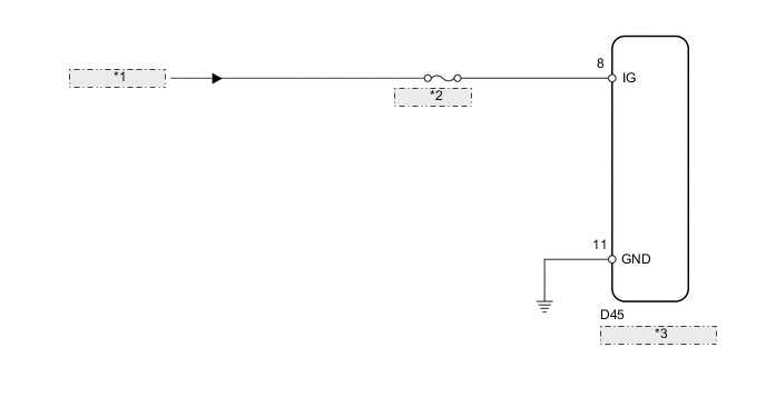
| *1 | from IG Circuit |
| *2 | ECU-IG NO. 3 |
| *3 | Multiplex Tilt and Telescopic ECU |
CAUTION / NOTICE / HINT
Note
Inspect the fuses for circuits related to this system before performing the following inspection procedure.
PROCEDURE
-
CHECK HARNESS AND CONNECTOR (MULTIPLEX TILT AND TELESCOPIC ECU - BATTERY)
-
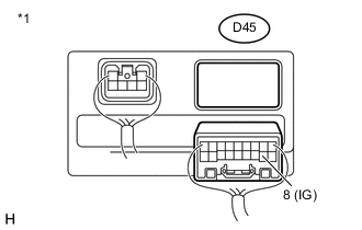
Text in Illustration *1 Rear view of wire harness connector
(to Multiplex Tilt and Telescopic ECU)
Disconnect the D45 multiplex tilt and telescopic ECU connector.
-
Measure the voltage according to the value(s) in the table below.
Standard Voltage Tester Connection Switch Condition Specified Condition D45-8 (IG) - Body ground Engine switch on (IG) 11 to 14 V
NG 
REPAIR OR REPLACE HARNESS OR CONNECTOR
OK 
-
-
CHECK HARNESS AND CONNECTOR (MULTIPLEX TILT AND TELESCOPIC ECU - BODY GROUND)
-
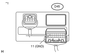
Text in Illustration *1 Rear view of wire harness connector
(to Multiplex Tilt and Telescopic ECU)
Measure the resistance according to the value(s) in the table below.
Standard Resistance Tester Connection Condition Specified Condition D45-11 (GND) - Body ground Always Below 1 Ω
OK
REPLACE MULTIPLEX TILT AND TELESCOPIC ECU Click here
NG
REPAIR OR REPLACE HARNESS OR CONNECTOR
-