BRAKE PEDAL STROKE SENSOR INSTALLATION
PROCEDURE
-
INSTALL BRAKE PEDAL STROKE SENSOR ASSEMBLY (CLUTCH PEDAL STROKE SENSOR)
Note
Do not drop the sensor. If the sensor has been dropped, replace the sensor with a new one.
-
When installing a new brake pedal stroke sensor assembly (clutch pedal stroke sensor):
Note
Do not break the sensor lever set pin before installing the brake pedal stroke sensor (clutch pedal stroke sensor) with the bolts. If the sensor lever set pin breaks while tightening the bolt, do not use that sensor.
-
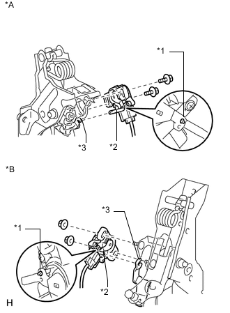
Text in Illustration *A for LHD *B for RHD *1 Pin *2 Lever *3 Groove Connect the sensor connector.
-
for LHD:
Install a new sensor with the 2 bolts.
- Torque:
- 8.5 N*m { 87 kgf*cm, 75 in.*lbf }
Note
-
Engage the sensor lever with the clutch pedal groove.
-
Check that there is no foreign matter attached to the contact surface of the sensor.
-
Check that the tip of the sensor lever is protruding from the clutch pedal groove.
-
for RHD:
Install a new sensor with the 2 nuts.
- Torque:
- 8.5 N*m { 87 kgf*cm, 75 in.*lbf }
Note
-
Engage the sensor lever with the clutch pedal groove.
-
Check that there is no foreign matter attached to the contact surface of the sensor.
-
Check that the tip of the sensor lever is protruding from the clutch pedal groove.
-
Firmly depress the clutch pedal and break the pin.
-
Remove the broken pin.
-
-
When reusing the brake pedal stroke sensor assembly (clutch pedal stroke sensor):
-
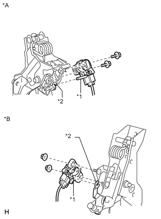
Text in Illustration *A for LHD *B for RHD *1 Lever *2 Groove Connect the sensor connector.
Note
Do not drop the sensor. If the sensor has been dropped, replace the sensor with a new one.
-
for LHD:
Temporarily install the sensor with the 2 bolts.
Note
-
Engage the sensor lever with the clutch pedal groove.
-
Check that there is no foreign matter attached to the contact surface of the sensor.
-
-
for RHD:
Temporarily install the sensor with the 2 nuts.
Note
-
Engage the sensor lever with the clutch pedal groove.
-
Check that there is no foreign matter attached to the contact surface of the sensor.
-
-
Connect the cable to the negative battery terminal.
-
Connect the intelligent tester to the DLC3.
-
Turn the ignition switch to ON.
-
Turn the intelligent tester on.
-
Enter the following menus: Chassis / Electric Parking Brake / Data List.
-
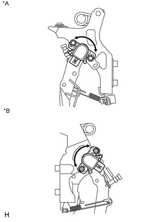
Text in Illustration *A for LHD *B for RHD While reading the value of the stroke sensor shown in the Data List, turn the sensor slowly to the right and left to adjust the output voltage to the standard voltage.
Standard Voltage Tester Display Measurement Item/Range Normal Condition Diagnostic Note SKS1 Raw Value of AD Brake pedal stroke sensor (Clutch pedal stroke sensor)(SKS1) voltage display /
Min.: 0 V
Max.: 5 V
When clutch pedal is released: 0.8 to 1.2 V - -
for LHD:
Tighten the 2 bolts.
- Torque:
- 8.5 N*m { 87 kgf*cm, 75 in.*lbf }
Note
Do not depress the clutch pedal after turning the ignition switch to ON.
-
for RHD:
Tighten the 2 nuts.
- Torque:
- 8.5 N*m { 87 kgf*cm, 75 in.*lbf }
Note
Do not depress the clutch pedal after turning the ignition switch to ON.
-
Turn the ignition switch off.
-
Disconnect the cable from the negative battery terminal.
-
Disconnect the intelligent tester.
-
-
-
INSTALL LOWER NO. 1 INSTRUMENT PANEL AIRBAG ASSEMBLY
-
Install the lower No. 1 instrument panel airbag assembly Click here.
-
-
CONNECT CABLE TO NEGATIVE BATTERY TERMINAL
Note
When disconnecting the cable, some systems need to be initialized after the cable is reconnected Click here.
-
CHECK SRS WARNING LIGHT
-
Check the SRS warning light Click here.
-
-
CHECK AND CLEAR DTC
-
Check and clear the DTCs Click here.
-
-
PERFORM BRAKE PEDAL STROKE SENSOR (CLUTCH PEDAL STROKE SENSOR) ZERO POINT CALIBRATION
-
Perform the brake pedal stroke sensor (clutch pedal stroke sensor) zero point calibration Click here.
-
-
PERFORM CLUTCH ENGAGEMENT POINT LEARNING