VEHICLE STABILITY CONTROL SYSTEM TERMINALS OF ECU

-
TERMINALS OF ECU
-
for CVT

Text in Illustration *a Component without harness connected
(Skid Control ECU (Brake Actuator Assembly))
- - Terminal No. (Symbol) Terminal Description 1 (+BM) Motor relay power supply 2 (SP1) Speed signal output for speedometer 3 (STPO) Stop light control relay output 4 (FR-) Front wheel speed RH (-) signal input 5 - (Not used) 6 - (Not used) 7 - (Not used) 8 (FL-) Front wheel speed LH (-) signal input 9 (CSW) VSC OFF switch input 10 - (Not used) 11 - (Not used) 12 - (Not used) 13 (GND2) Pump motor ground 14 (CANL) CAN communication line L 15 - (Not used) 16 (FR+) Front wheel speed RH (+) signal input 17 (RR+) Rear wheel speed RH (+) signal input 18 (RL-) Rear wheel speed LH (-) signal input 19 (FL+) Front wheel speed LH (+) signal input 20 - (Not used) 21 - (Not used) 22 (STP2) Stop light control relay signal input 23 - (Not used) 24 - (Not used) 25 (+BS) ABS solenoid relay power supply 26 (CANH) CAN communication line H 27 (TS) Sensor check input 28 (IG1) IG1 power source input 29 (RR-) Rear wheel speed RH (-) signal input 30 (STP) Stop light switch assembly input 31 (RL+) Rear wheel speed LH (+) signal input 32 - (Not used) 33 - (Not used) 34 - (Not used) 35 - (Not used) 36 - (Not used) 37 - (Not used) 38 (GND1) Skid control ECU ground -
for A/T or M/T

Text in Illustration *a Component without harness connected
(Skid Control ECU (Brake Actuator Assembly))
- - Terminal No. (Symbol) Terminal Description 1 (+BS) ABS solenoid relay power supply 2 (CANH) CAN communication line H 3 (TS) Sensor check input 4 (IG1) IG1 power source input 5 (RR-) Rear wheel speed RH (-) signal input 6 (STP) Stop light switch assembly input 7 (RL+) Rear wheel speed LH (+) signal input 8 - (Not used) 9 - (Not used) 10 - (Not used) 11 - (Not used) 12 - (Not used) 13 - (Not used) 14 (GND1) Skid control ECU ground 15 (+BM) Motor relay power supply 16 (CANL) CAN communication line L 17 - (Not used) 18 (FR+) Front wheel speed RH (+) signal input 19 (RR+) Rear wheel speed RH (+) signal input 20 (RL-) Rear wheel speed LH (-) signal input 21 (FL+) Front wheel speed LH (+) signal input 22 - (Not used) 23 - (Not used) 24 (STP2) Stop light control relay signal input 25 - (Not used) 26 - (Not used) 27 (SP1) Speed signal output for speedometer 28 (STPO) Stop light control relay output 29 (FR-) Front wheel speed RH (-) signal input 30 - (Not used) 31 - (Not used) 32 - (Not used) 33 (FL-) Front wheel speed LH (-) signal input 34 (CSW) VSC OFF switch input 35 - (Not used) 36 - (Not used) 37 - (Not used) 38 (GND2) Pump motor ground
-
-
TERMINAL INSPECTION
-
for CVT
-
Disconnect the connector and measure the voltage and resistance on the wire harness side.
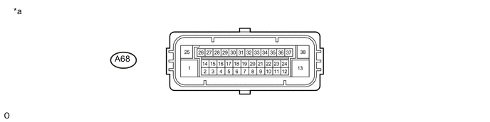
Text in Illustration *a Front view of wire harness connector
(to Skid Control ECU (Brake Actuator Assembly))
- - Tech Tips
The voltage cannot be measured with the connector connected to the skid control ECU (brake actuator assembly) because the connector is watertight.
Standard Terminal No. (Symbol) Wiring Color Terminal Description Condition Specified Condition A68-1 (+BM) - Body ground L - Body ground Motor relay power supply Always 11 to 14 V A68-9 (CSW) - Body ground P - Body ground VSC OFF switch input VSC OFF switch ON → OFF (Pressed → not pressed) Below 1 Ω → 10 kΩ or higher A68-13 (GND2) - Body ground W-B - Body ground Pump motor ground Always Below 1 Ω A68-22 (STP2) - Body ground L- Body ground Stop light switch assembly (stop light control relay) input Stop light switch assembly ON → OFF (Brake pedal depressed → released) 11 to 14 V → Below 1.5 V A68-25 (+BS) - Body ground W - Body ground ABS solenoid relay power supply Always 11 to 14 V A68-28 (IG1) - Body ground G - Body ground IG1 power source input Ignition switch ON 11 to 14 V A68-30 (STP) - Body ground V - Body ground Stop light switch assembly input Stop light switch assembly ON → OFF (Brake pedal depressed → released) 11 to 14 V* → Below 1.5 V A68-38 (GND1) - Body ground W-B - Body ground Skid control ECU ground Always Below 1 Ω Tech Tips
*: The standard voltage value varies depending on the +BS terminal voltage value. The standard voltage is 85% of the +BS terminal voltage.
-
-
for A/T or M/T
-
Disconnect the connector and measure the voltage and resistance on the wire harness side.
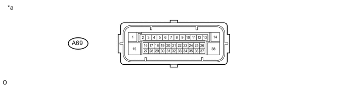
Text in Illustration *a Front view of wire harness connector
(to Skid Control ECU (Brake Actuator Assembly))
- - Tech Tips
The voltage cannot be measured with the connector connected to the skid control ECU (brake actuator assembly) because the connector is watertight.
Standard Terminal No. (Symbol) Wiring Color Terminal Description Condition Specified Condition A69-1 (+BS) - Body ground W - Body ground ABS solenoid relay power supply Always 11 to 14 V A69-4 (IG1) - Body ground G - Body ground IG1 power source input Ignition switch ON 11 to 14 V A69-6 (STP) - Body ground V - Body ground Stop light switch assembly input Stop light switch assembly ON → OFF (Brake pedal depressed → released) 11 to 14 V* → Below 1.5 V A69-14 (GND1) - Body ground W-B - Body ground Skid control ECU ground Always Below 1 Ω A69-15 (+BM) - Body ground L - Body ground Motor relay power supply Always 11 to 14 V A69-24 (STP2) - Body ground L- Body ground Stop light switch assembly (stop light control relay) input Stop light switch assembly ON → OFF (Brake pedal depressed → released) 11 to 14 V → Below 1.5 V A69-34 (CSW) - Body ground P - Body ground VSC OFF switch input VSC OFF switch ON → OFF (Pressed → not pressed) Below 1 Ω → 10 kΩ or higher A69-38 (GND2) - Body ground W-B - Body ground Pump motor ground Always Below 1 Ω Tech Tips
*: The standard voltage value varies depending on the +BS terminal voltage value. The standard voltage is 85% of the +BS terminal voltage.
-
-