VEHICLE STABILITY CONTROL SYSTEM TEST MODE PROCEDURE

-
WARNING LIGHT AND INDICATOR LIGHT INITIAL CHECK
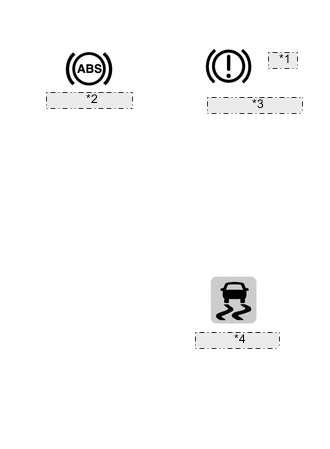
*1 (RED) *2 ABS Warning Light *3 Brake System Warning Light (Red Indicator) *4 Slip Indicator Light
-
Release the parking brake.
CAUTION:
When releasing the parking brake, set chocks to hold the vehicle for safety.
-
When the ignition switch is ON, check that the ABS warning light, brake system warning light (red indicator) and slip indicator light come on for approximately 3 seconds. If a light remains on, proceed to troubleshooting for the light circuit below.
Trouble Area See procedure ABS warning light circuit (Remains on) ABS warning light circuit (Does not come on) Brake system warning light (red indicator) circuit (Remains on) Brake system warning light (red indicator) circuit (Does not come on) Slip indicator light circuit (Remains on) Slip indicator light circuit (Does not come on)
-
-
SENSOR CHECK USING TEST MODE (SIGNAL CHECK) (Using the Intelligent Tester)
Tech Tips
If the ignition switch is turned from ON to ACC or off during Test Mode (signal check), DTCs stored during the sensor check will be cleared.
-
Procedure to enter Test Mode.
-
Turn the ignition switch off.
-
Check that the steering wheel is in the straight-ahead position.
-
Check that the shift lever is in P (for A/T, CVT) or the parking brake is applied (for M/T).
-
Connect the intelligent tester to the DLC3.
-
Turn the ignition switch to ON.
-
Turn the intelligent tester on.
-
Switch the skid control ECU to Test Mode using the intelligent tester. Enter the following menus: Chassis / ABS/VSC/TRC / Utility / Signal Check.
-
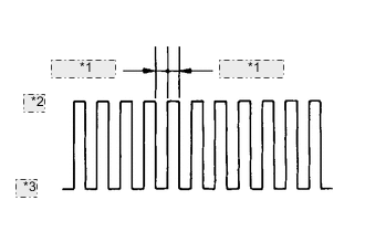
Test Mode Blinking Pattern *1 0.125 sec. *2 ON *3 OFF Check that the ABS warning light and slip indicator light come on for several seconds and then blink in the Test Mode pattern.
If the ABS warning light and slip indicator light do not blink, inspect the TS and CG terminal circuit, and ABS warning light and slip indicator light circuits.
Trouble Area See procedure TS and CG terminal circuit ABS warning light circuit (Remains on) ABS warning light circuit (Does not come on) Slip indicator light circuit (Remains on) Slip indicator light circuit (Does not come on)
-
-
-
SENSOR CHECK (Using the Intelligent Tester)
-
Check speed sensor.
-
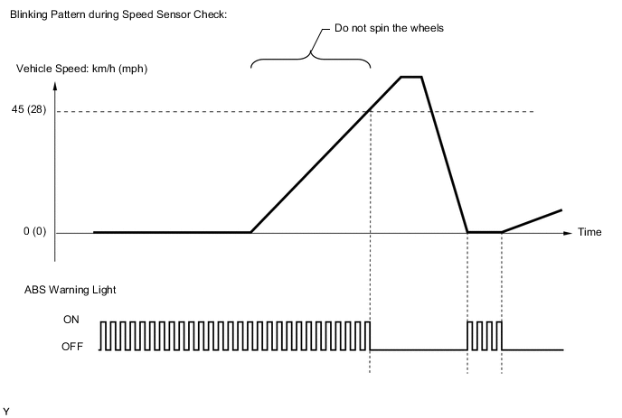
Drive the vehicle straight ahead and accelerate it to a speed of 45 km/h (28 mph) or more over several seconds.
-
Check that the ABS warning light goes off.
-
Stop the vehicle.
Note
-
The speed sensor check may not be completed if the speed sensor check is started while turning the steering wheel or spinning the wheels.
-
If the sensor check has not been completed, the ABS warning light will blink while driving and the anti-lock brake system will not operate.
Tech Tips
When the sensor check has been completed, the ABS warning light goes off while driving and blinks in the Test Mode pattern while stationary.
-
-
-
Check VSC OFF switch.
-
Briefly press the VSC OFF switch.
-
Check that the TRC OFF message on the multi-information display changes from displayed to not displayed.
-
Briefly press the VSC OFF switch again.
-
Check that the TRC OFF message on the multi-information display changes from not displayed to displayed.
-
-
-
END OF SENSOR CHECK (Using the Intelligent Tester)
-
Test Mode Blinking Pattern *1 0.125 sec. *2 ON *3 OFF If the sensor check is completed, the ABS warning light blinks (Test Mode) when the vehicle stops and is off while the vehicle is being driven.
Note
If the sensor check is not completed, the ABS warning light blinks even while the vehicle is being driven and the ABS does not operate.
-
-
READ DTC OF SENSOR CHECK FUNCTION (Using the Intelligent Tester)
-
Read the DTC(s) by following the intelligent tester screen.
Note
-
If only DTCs are displayed, repair the malfunctions and clear the DTCs.
-
If DTCs and Test Mode codes (DTCs of the sensor check function) are displayed, repair the malfunctions, clear the DTCs and perform the Test Mode inspection.
Tech Tips
Refer to the list of DTCs Click here.
-
-
-
SENSOR CHECK USING TEST MODE (SIGNAL CHECK) (Using SST Check Wire)
Tech Tips
If the ignition switch is turned from ON to ACC or off during Test Mode (signal check), DTCs stored during the sensor check will be cleared.
-
Procedure to enter Test Mode.
-
Turn the ignition switch off.
-
Check that the steering wheel is in the straight-ahead position.
-
Check that the shift lever is in P (for A/T, CVT) or the parking brake is applied (for M/T).
-
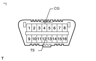
Text in Illustration *1 Front view of DLC3 Using SST, connect terminals 12 (TS) and 4 (CG) of the DLC3.
- SST
- 09843-18040
-
Turn the ignition switch to ON.
-
Test Mode Blinking Pattern *1 0.125 sec. *2 ON *3 OFF Check that the ABS warning light and slip indicator light come on for several seconds and then blink in the Test Mode pattern.
If the ABS warning light and slip indicator light do not blink, inspect the TS and CG terminal circuit, and ABS warning light and slip indicator light circuits.
Trouble Area See procedure TS and CG terminal circuit ABS warning light circuit (Remains on) ABS warning light circuit (Does not come on) Slip indicator light circuit (Remains on) Slip indicator light circuit (Does not come on)
-
-
-
SENSOR CHECK (Using SST Check Wire)
-
Check speed sensor.
-
Drive the vehicle straight ahead and accelerate it to a speed of 45 km/h (28 mph) or more over several seconds.
-
Check that the ABS warning light goes off.
-
Stop the vehicle.
Note
-
The speed sensor check may not be completed if the speed sensor check is started while turning the steering wheel or spinning the wheels.
-
If the sensor check has not been completed, the ABS warning light will blink while driving and the anti-lock brake system will not operate.
Tech Tips
When the sensor check has been completed, the ABS warning light goes off while driving and blinks in the Test Mode pattern while stationary.
-
-
-
Check VSC OFF switch.
-
Briefly press the VSC OFF switch.
-
Check that the TRC OFF message on the multi-information display changes from displayed to not displayed.
-
Briefly press the VSC OFF switch again.
-
Check that the TRC OFF message on the multi-information display changes from not displayed to displayed.
-
-
-
END OF SENSOR CHECK (Using SST Check Wire)
-
Test Mode Blinking Pattern *1 0.125 sec. *2 ON *3 OFF If the sensor check is completed, the ABS warning light blinks (Test Mode) when the vehicle stops and is off while the vehicle is driving.
Note
If the sensor check is not completed, the ABS warning light blinks even while the vehicle is driving and the ABS does not operate.
-
-
READ DTC OF SENSOR CHECK FUNCTION (Using SST Check Wire)
-
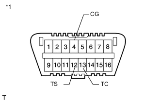
Text in Illustration *1 Front view of DLC3 Using SST, connect terminals 13 (TC) and 4 (CG) of the DLC3.
- SST
- 09843-18040
-
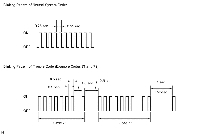
Count the number of blinks of the ABS warning light.
Note
-
If only DTCs are displayed, repair the malfunctions and clear the DTCs.
-
If DTCs and Test Mode codes (DTCs of the sensor check function) are displayed, repair the malfunctions, clear the DTCs and perform the Test Mode inspection.
Tech Tips
-
If more than 1 malfunction is detected at the same time, the lowest numbered code will be displayed first.
-
Refer to the list of DTCs Click here.
-
-
After performing the check, disconnect SST from terminals 12 (TS) and 4 (CG), and 13 (TC) and 4 (CG) of the DLC3, and turn the ignition switch off.
-
Turn the ignition switch to ON to cancel the Test Mode.
Tech Tips
-
If the ignition switch is not turned to ON after SST is removed from the DLC3, the previous Test Mode will continue.
-
If the ignition switch is turned to ON with terminals 12 (TS) and 4 (CG) connected, the previous Test Mode will continue.
-
-
-
DTC OF SENSOR CHECK FUNCTION
ABS Sensor DTC Code Detection Item Trouble Area C1271/71 Low output signal of front speed sensor RH
-
Front speed sensor RH
-
Sensor installation
-
Speed sensor rotor (Front axle hub sub-assembly RH)
C1272/72 Low output signal of front speed sensor LH
-
Front speed sensor LH
-
Sensor installation
-
Speed sensor rotor (Front axle hub sub-assembly LH)
C1273/73 Low output signal of rear speed sensor RH
-
Rear speed sensor RH (Rear axle hub and bearing assembly RH)
-
Sensor installation
-
Speed sensor rotor (Rear axle hub and bearing assembly RH)
C1274/74 Low output signal of rear speed sensor LH
-
Rear speed sensor LH (Rear axle hub and bearing assembly LH)
-
Sensor installation
-
Speed sensor rotor (Rear axle hub and bearing assembly LH)
C1275/75 Abnormal change in output signal of front speed sensor RH Speed sensor rotor (Front axle hub sub-assembly RH) C1276/76 Abnormal change in output signal of front speed sensor LH Speed sensor rotor (Front axle hub sub-assembly LH) C1277/77 Abnormal change in output signal of rear speed sensor RH Speed sensor rotor (Rear axle hub and bearing assembly RH) C1278/78 Abnormal change in output signal of rear speed sensor LH Speed sensor rotor (Rear axle hub and bearing assembly LH) Tech Tips
The codes in this table are output only in Test Mode (signal check).
-