FRONT SUSPENSION MEMBER INSTALLATION

PROCEDURE
-
INSTALL FRONT SUSPENSION MEMBER BODY FRONT MOUNTING CUSHION
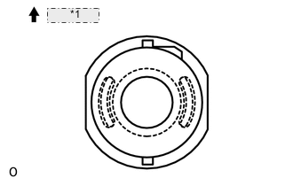
*1 Front Side
-
Temporarily install 2 new cushions to the front suspension member shown in the illustration.
-
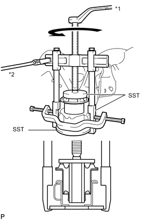
Text in Illustration *1 Turn *2 Hold Using SST, install the 2 cushions so that there is no clearance between the suspension member and cushion.
- SST
- 09570-24011
- 09950-40011 ( 09951-04020, 09952-04010, 09953-04030, 09954-04020, 09955-04061, 09957-04010, 09958-04011 )
- 09950-60020 ( 09951-00710 )
Note
-
Apply a small amount of grease to the threads of SST (center bolt) before use.
-
Do not apply excessive pressure to the center sleeve of the cushion.
-
-
INSTALL FRONT SUSPENSION MEMBER BODY REAR MOUNTING CUSHION
-
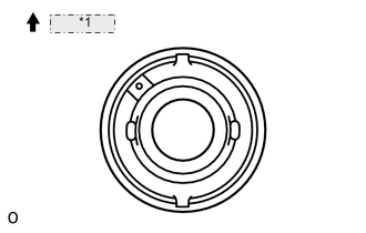
*1 Front Side Temporarily install 2 new cushions to the front suspension member shown in the illustration.
-
Text in Illustration *1 Turn *2 Hold Using SST, install the 2 cushions so that there is no clearance between the suspension member and cushion.
- SST
- 09570-24011
- 09950-40011 ( 09951-04020, 09952-04010, 09953-04030, 09954-04020, 09955-04061, 09957-04010, 09958-04011 )
- 09950-60020 ( 09951-00710 )
Note
-
Apply a small amount of grease to the threads of SST (center bolt) before use.
-
Do not apply excessive pressure to the center sleeve of the cushion.
-
-
INSTALL CAB REAR MOUNTING CUSHION
-
Install 4 new cushions to the suspension member.
-
-
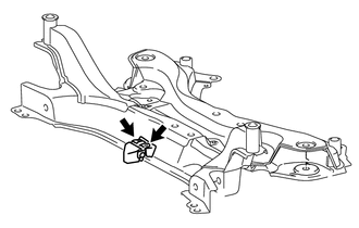
INSTALL FRONT SUSPENSION MEMBER DYNAMIC DAMPER
-
Install the dynamic damper to the suspension member with the 2 bolts.
- Torque:
- 32 N*m { 326 kgf*cm, 24 ft.*lbf }
-
-
INSTALL STEERING LINK ASSEMBLY
-
INSTALL FRONT STABILIZER BAR
-
INSTALL FRONT SUSPENSION MEMBER FRONT BRACE LH
-
INSTALL FRONT SUSPENSION MEMBER FRONT BRACE RH
-
TEMPORARILY INSTALL FRONT NO. 1 LOWER SUSPENSION ARM SUB-ASSEMBLY LH
-
TEMPORARILY INSTALL FRONT NO. 1 LOWER SUSPENSION ARM SUB-ASSEMBLY RH
Tech Tips
Perform the same procedure as for the LH side.
-
INSTALL FRONT SUSPENSION CROSSMEMBER SUB-ASSEMBLY
-
INSTALL FRONT SUSPENSION MEMBER REAR BRACE LH
-
INSTALL FRONT SUSPENSION MEMBER REAR BRACE RH
-
INSTALL FRONT SUSPENSION MEMBER REINFORCEMENT LH
-
INSTALL FRONT SUSPENSION MEMBER REINFORCEMENT RH
-
CONNECT FRONT NO. 1 LOWER SUSPENSION ARM SUB-ASSEMBLY LH
-
CONNECT FRONT NO. 1 LOWER SUSPENSION ARM SUB-ASSEMBLY RH
Tech Tips
Perform the same procedure as for the LH side.
-
CONNECT TIE ROD END SUB-ASSEMBLY LH
-
CONNECT TIE ROD END SUB-ASSEMBLY RH
Tech Tips
Perform the same procedure as for the LH side.
-
CONNECT FRONT STABILIZER LINK ASSEMBLY LH
-
CONNECT FRONT STABILIZER LINK ASSEMBLY RH
Tech Tips
Perform the same procedure as for the LH side.
-
INSTALL NO. 1 STEERING COLUMN HOLE COVER SUB-ASSEMBLY
-
CONNECT NO. 2 STEERING INTERMEDIATE SHAFT ASSEMBLY
-
INSTALL COLUMN HOLE COVER SILENCER SHEET
-
INSTALL REAR ENGINE UNDER COVER LH
-
INSTALL REAR ENGINE UNDER COVER RH
Tech Tips
Perform the same procedure as for the LH side.
-
INSTALL FRONT WHEELS
- Torque:
- 103 N*m { 1050 kgf*cm, 76 ft.*lbf }
-
STABILIZE SUSPENSION
-
INSTALL NO. 2 ENGINE UNDER COVER
-
INSTALL CENTER NO. 4 ENGINE UNDER COVER
-
INSTALL NO. 1 ENGINE UNDER COVER
-
INSTALL NO. 1 ENGINE UNDER COVER (for Rough Road Area Specification Vehicles)
-
INSTALL FRONT BUMPER ABSORBER LOWER COVER
-
TIGHTEN FRONT NO. 1 LOWER SUSPENSION ARM SUB-ASSEMBLY LH
-
TIGHTEN FRONT NO. 1 LOWER SUSPENSION ARM SUB-ASSEMBLY RH
Tech Tips
Perform the same procedure as for the LH side.
-
INSPECT AND ADJUST FRONT WHEEL ALIGNMENT
-
Inspect and adjust the front wheel alignment Click here.
-
-
ADJUST HEADLIGHT ASSEMBLY
-
for Halogen Headlight:
Adjust the headlight assembly Click here.
-
for LED Headlight:
Adjust the headlight assembly Click here.
-