REAR SUSPENSION MEMBER INSTALLATION

PROCEDURE
-
INSTALL REAR SUSPENSION MEMBER DYNAMIC DAMPER
-
Install the 2 dynamic dampers to the rear suspension member with the 4 bolts.
- Torque:
- 35 N*m { 357 kgf*cm, 26 ft.*lbf }
-
-
INSTALL REAR SUSPENSION MEMBER FRONT BODY MOUNTING CUSHION (w/o Rough Road Package 2)
-
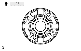
*1 Front Side Temporarily install 2 new cushions to the rear suspension member facing in the direction shown in the illustration.
-
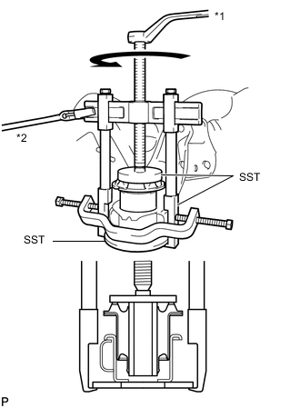
Text in Illustration *1 Turn *2 Hold Using SST, install the cushion so that there is no clearance between the suspension member and cushion.
- SST
- 09570-24011
- 09950-40011 ( 09951-04020, 09952-04010, 09953-04030, 09954-04020, 09955-04061, 09957-04010, 09958-04011 )
- 09950-60020 ( 09951-00710 )
Note
-
Apply a small amount of grease to the threads of SST (center bolt) before use.
-
Do not apply excessive pressure to the center sleeve of the cushion.
-
-
INSTALL REAR SUSPENSION MEMBER REAR BODY MOUNT CUSHION (w/o Rough Road Package 2)
-
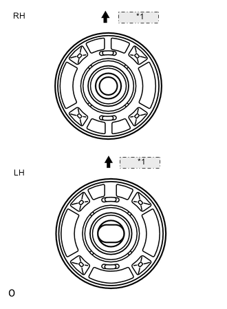
*1 Front Side Temporarily install 2 new cushions to the rear suspension member facing in the direction shown in the illustration.
-
Text in Illustration *1 Turn *2 Hold Using SST, install the cushion so that there is no clearance between the suspension member and cushion.
- SST
- 09570-24011
- 09950-40011 ( 09951-04020, 09952-04010, 09953-04030, 09954-04020, 09955-04061, 09957-04010, 09958-04011 )
- 09950-60020 ( 09951-00710 )
Note
-
Apply a small amount of grease to the threads of SST (center bolt) before use.
-
Do not apply excessive pressure to the center sleeve of the cushion.
-
-
INSTALL PARKING BRAKE ACTUATOR SUPPORT BRACKET
-
INSTALL PARKING BRAKE WITH CABLE ACTUATOR ASSEMBLY
-
INSTALL REAR SUSPENSION MEMBER SUB-ASSEMBLY
CAUTION:
As the rear suspension member is very heavy, support it with an engine lift and attachments.
-
Lift the rear suspension member with an engine lift and attachments.
-
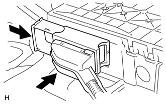
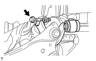
Connect the electrical parking brake actuator connector and push in the lock lever.
-
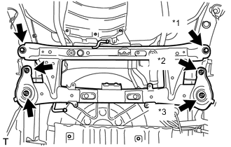
Text in Illustration *1 Bolt *2 Nut A *3 Nut B Install the rear suspension member and 8 rear suspension member stoppers with the 2 bolts and 4 nuts.
- Torque:
- for bolt
- 125 N*m { 1275 kgf*cm, 92 ft.*lbf }
- for nut A
- 61 N*m { 620 kgf*cm, 45 ft.*lbf }
- for nut B
- 125 N*m { 1275 kgf*cm, 92 ft.*lbf }
-
-
TEMPORARILY INSTALL REAR UPPER CONTROL ARM ASSEMBLY LH
-
Temporarily install the upper control arm to the rear suspension member with the bolt and nut.
-
-
TEMPORARILY INSTALL REAR UPPER CONTROL ARM ASSEMBLY RH
Tech Tips
Use the same procedure described for the LH side.
-
TEMPORARILY INSTALL REAR NO. 2 SUSPENSION ARM ASSEMBLY LH
-
TEMPORARILY INSTALL REAR NO. 2 SUSPENSION ARM ASSEMBLY RH
Tech Tips
Use the same procedure described for the LH side.
-
INSTALL REAR LOWER COIL SPRING INSULATOR LH
-
INSTALL REAR LOWER COIL SPRING INSULATOR RH
-
INSTALL REAR UPPER COIL SPRING INSULATOR LH
-
INSTALL REAR UPPER COIL SPRING INSULATOR RH
Tech Tips
Use the same procedure described for the LH side.
-
INSTALL REAR COIL SPRING LH
-
INSTALL REAR COIL SPRING RH
Tech Tips
Use the same procedure described for the LH side.
-
TEMPORARILY INSTALL REAR SHOCK ABSORBER ASSEMBLY LH
-
TEMPORARILY INSTALL REAR SHOCK ABSORBER ASSEMBLY RH
Tech Tips
Use the same procedure described for the LH side.
-
INSTALL REAR AXLE CARRIER SUB-ASSEMBLY LH
-
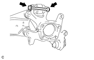
Install the rear axle carrier to the rear upper control arm with the bolt and nut.
- Torque:
- 90 N*m { 918 kgf*cm, 66 ft.*lbf }
Note
Since a stopper nut is used, tighten the bolt.
-
-
INSTALL REAR AXLE CARRIER SUB-ASSEMBLY RH
Tech Tips
Use the same procedure described for the LH side.
-
TEMPORARILY INSTALL REAR NO. 1 SUSPENSION ARM ASSEMBLY LH
-
TEMPORARILY INSTALL REAR NO. 1 SUSPENSION ARM ASSEMBLY RH
Tech Tips
Use the same procedure described for the LH side.
-
CONNECT REAR TRAILING ARM ASSEMBLY LH
-
Connect the rear trailing arm to the rear axle carrier with the 2 bolts.
- Torque:
- 200 N*m { 2039 kgf*cm, 148 ft.*lbf }
-
-
CONNECT REAR TRAILING ARM ASSEMBLY RH
Tech Tips
Use the same procedure described for the LH side.
-
INSTALL REAR STABILIZER BAR
-
INSTALL REAR STABILIZER LINK ASSEMBLY LH
-
INSTALL REAR STABILIZER LINK ASSEMBLY RH
Tech Tips
Use the same procedure described for the LH side.
-
INSTALL REAR SUSPENSION MEMBER BRACE LH
-
INSTALL REAR SUSPENSION MEMBER BRACE RH
Tech Tips
Use the same procedure described for the LH side.
-
INSTALL REAR FLOOR SIDE MEMBER COVER RH
-
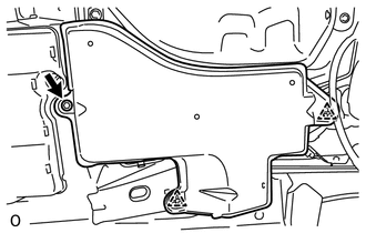
Attach the 2 clips to install the rear floor side member cover RH, and then install the bolt.
- Torque:
- 13 N*m { 127 kgf*cm, 9 ft.*lbf }
-
-
INSTALL REAR SUSPENSION ARM COVER LH
-
INSTALL REAR SUSPENSION ARM COVER RH
Tech Tips
Use the same procedure described for the LH side.
-
INSTALL REAR HEIGHT CONTROL SENSOR SUB-ASSEMBLY (for LED Headlight)
-
INSTALL REAR AXLE HUB AND BEARING ASSEMBLY LH
-
INSTALL REAR AXLE HUB AND BEARING ASSEMBLY RH
Tech Tips
Use the same procedure described for the LH side.
-
INSTALL REAR DISC
-
CONNECT REAR DISC BRAKE CALIPER ASSEMBLY LH
-
CONNECT REAR DISC BRAKE CALIPER ASSEMBLY RH
Tech Tips
Use the same procedure described for the LH side.
-
CONNECT PARKING BRAKE CABLE AND EMERGENCY RELEASE CABLE
-
INSTALL FLOOR NO. 2 UNDER COVER
-
Install the floor No. 2 under cover with the 6 clips.
-
-
CONNECT SKID CONTROL SENSOR WIRE
-
INSTALL TAILPIPE ASSEMBLY
-
for 3ZR-FE:
Install the tailpipe assembly Click here.
-
for 1ZR-FAE:
Install the tailpipe assembly Click here.
-
for 2ZR-FAE:
Install the tailpipe assembly Click here.
-
for 3ZR-FAE:
Install the tailpipe assembly Click here.
-
-
STABILIZE SUSPENSION
-
TIGHTEN REAR SHOCK ABSORBER ASSEMBLY LH
-
TIGHTEN REAR SHOCK ABSORBER ASSEMBLY RH
Tech Tips
Use the same procedure described for the LH side.
-
TIGHTEN REAR UPPER CONTROL ARM ASSEMBLY LH
-
TIGHTEN REAR UPPER CONTROL ARM ASSEMBLY RH
Tech Tips
Use the same procedure described for the LH side.
-
TIGHTEN REAR NO. 2 SUSPENSION ARM ASSEMBLY LH
-
TIGHTEN REAR NO. 2 SUSPENSION ARM ASSEMBLY RH
Tech Tips
Use the same procedure described for the LH side.
-
TIGHTEN REAR NO. 1 SUSPENSION ARM ASSEMBLY LH
-
TIGHTEN REAR NO. 1 SUSPENSION ARM ASSEMBLY RH
Tech Tips
Use the same procedure described for the LH side.
-
CONNECT CABLE TO NEGATIVE BATTERY TERMINAL
Note
When disconnecting the cable, some systems need to be initialized after the cable is reconnected Click here.
-
INSTALL REAR WHEEL
- Torque:
- 103 N*m { 1050 kgf*cm, 76 ft.*lbf }
-
INSPECT FOR EXHAUST GAS LEAK
-
INSPECT AND ADJUST REAR WHEEL ALIGNMENT
-
Inspect and adjust the rear wheel alignment Click here.
-
-
ADJUST HEADLIGHT ASSEMBLY
-
for Halogen Headlight:
Adjust the headlight assembly Click here.
-
for LED Headlight:
Adjust the headlight assembly Click here.
-
-
INSPECT SPEED SENSOR SIGNAL
-
PERFORM CALIBRATION
-
Clear the electric parking brake ECU memory and perform yaw rate sensor and clutch pedal stroke sensor zero point calibration Click here.
-