FRONT LOWER SUSPENSION ARM REMOVAL

PROCEDURE
-
REMOVE FRONT WHEELS
-
REMOVE FRONT BUMPER ABSORBER LOWER COVER
-
REMOVE NO. 1 ENGINE UNDER COVER
-
REMOVE NO. 1 ENGINE UNDER COVER (for Rough Road Area Specification Vehicles)
-
REMOVE CENTER NO. 4 ENGINE UNDER COVER
-
REMOVE REAR ENGINE UNDER COVER LH
-
Remove the 5 clips and under cover.
-
-
REMOVE REAR ENGINE UNDER COVER RH
Tech Tips
Perform the same procedure as for the LH side.
-
PLACE FRONT WHEELS FACING STRAIGHT AHEAD
-
SECURE STEERING WHEEL
-
REMOVE COLUMN HOLE COVER SILENCER SHEET
-
DISCONNECT NO. 2 STEERING INTERMEDIATE SHAFT ASSEMBLY
-
REMOVE NO. 1 STEERING COLUMN HOLE COVER SUB-ASSEMBLY
-
DISCONNECT FRONT STABILIZER LINK ASSEMBLY LH
-
Remove the nut and disconnect the stabilizer link assembly LH from the front stabilizer bar.
Tech Tips
If the ball joint turns together with the nut, use a 6 mm hexagon wrench to hold the stud bolt.
-
-
DISCONNECT FRONT STABILIZER LINK ASSEMBLY RH
Tech Tips
Perform the same procedure as for the LH side.
-
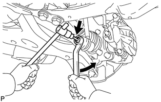
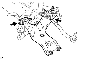
DISCONNECT TIE ROD END SUB-ASSEMBLY LH
-
DISCONNECT TIE ROD END SUB-ASSEMBLY RH
Tech Tips
Perform the same procedure as for the LH side.
-
LOOSEN FRONT NO. 1 LOWER SUSPENSION ARM SUB-ASSEMBLY LH
-
Loosen the bolt.
Note
Because the nut has its own stopper, do not turn the nut. Loosen the bolt with the nut fixed in place.
-
-
LOOSEN FRONT NO. 1 LOWER SUSPENSION ARM SUB-ASSEMBLY RH
Tech Tips
Perform the same procedure as for the LH side.
-
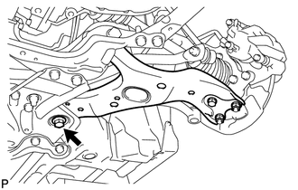
DISCONNECT FRONT NO. 1 LOWER SUSPENSION ARM SUB-ASSEMBLY LH
-
DISCONNECT FRONT NO. 1 LOWER SUSPENSION ARM SUB-ASSEMBLY RH
Tech Tips
Perform the same procedure as for the LH side.
-
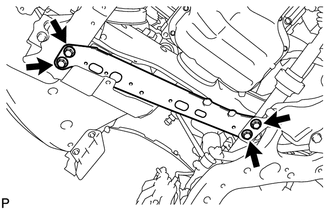
REMOVE FRONT SUSPENSION MEMBER REINFORCEMENT LH
-
Remove the 4 bolts and front suspension member reinforcement LH.
-
-
REMOVE FRONT SUSPENSION MEMBER REINFORCEMENT RH
-
Remove the 4 bolts and front suspension member reinforcement RH.
-
-
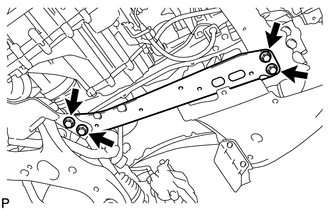
REMOVE FRONT SUSPENSION MEMBER REAR BRACE LH
-
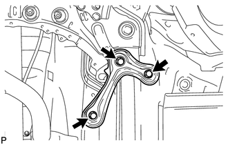
Remove the 3 bolts and front suspension member rear brace LH.
-
-
REMOVE FRONT SUSPENSION MEMBER REAR BRACE RH
Tech Tips
Perform the same procedure as for the LH side.
-
REMOVE FRONT SUSPENSION CROSSMEMBER SUB-ASSEMBLY
-
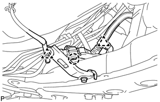
Detach the 2 clamps and claw, and disconnect the oxygen sensor wire from the front suspension crossmember.
-
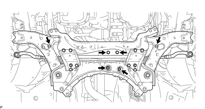
Support the front suspension crossmember with a transmission jack.
-
Remove the 4 bolts, 2 nuts and front suspension crossmember.
-
-
REMOVE FRONT NO. 1 LOWER SUSPENSION ARM SUB-ASSEMBLY LH
-
Remove the 2 bolts, nut and front lower suspension arm from the front suspension crossmember.
Note
Because the nut has its own stopper, do not turn the nut. Loosen the bolt with the nut fixed in place.
-