FRONT LOWER BALL JOINT REMOVAL

PROCEDURE
-
REMOVE FRONT WHEEL
-
REMOVE FRONT AXLE SHAFT NUT LH
-
DISCONNECT FRONT SPEED SENSOR LH
-
DISCONNECT FRONT FLEXIBLE HOSE
-
DISCONNECT TIE ROD END SUB-ASSEMBLY LH
-
DISCONNECT FRONT DISC BRAKE CALIPER ASSEMBLY LH
-
REMOVE FRONT DISC
-
DISCONNECT FRONT NO. 1 LOWER SUSPENSION ARM SUB-ASSEMBLY LH
-
REMOVE FRONT AXLE ASSEMBLY LH
-
REMOVE FRONT LOWER BALL JOINT ASSEMBLY LH
-
Secure the front axle assembly between aluminum plates in a vise.
Note
When using a vise, do not overtighten it.
-
Remove the cotter pin and nut.
-
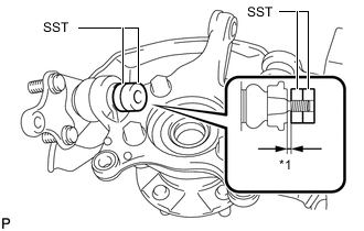
Text in Illustration *1 1 mm Install SST to the front lower ball joint as shown in the illustration.
- SST
- 09960-20010 ( 09961-02050, 09961-02050 )
Note
Make sure that the clearance measurement between SST and the front axle assembly is 1 mm (0.03937 in.).
-
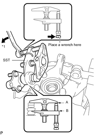
Text in Illustration *1 Turn Using SST, remove the front lower ball joint from the front axle assembly as shown in the illustration.
- SST
- 09960-20010 ( 09961-02010, 09961-02050, 09961-02050 )
Note
-
Install SST so that A and B are parallel.
-
Be sure to turn the part indicated in the illustration with a wrench.
-
Do not damage the front lower ball joint dust cover.
-