CONTINUOUSLY VARIABLE TRANSAXLE SYSTEM, Diagnostic DTC:P282B
| DTC Code | DTC Name |
|---|---|
| P282B | Pressure Control Solenoid "K" Electrical (Shift Solenoid Valve SLS) |
DESCRIPTION
According to current control by the ECM, the shift solenoid valve SLS controls secondary pulley pressure and belt clamping pressure in accordance with the input shaft torque.
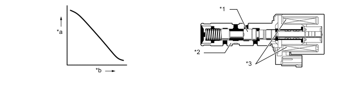
| *1 | Spool Valve | *2 | Sleeve |
| *3 | Solenoid Coil | - | - |
| *a | Hydraulic Pressure | *b | Current Flow to Solenoid |
| DTC Code | DTC Detection Condition
|
Trouble Area |
|---|---|---|
| P282B |
|
|
MONITOR DESCRIPTION
This DTC indicates an open or short circuit in the shift solenoid valve SLS circuit. If there is an open or short circuit in the shift solenoid valve SLS circuit, the ECM detects the problem, illuminates the MIL and stores this DTC.
WIRING DIAGRAM
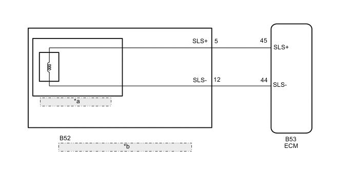
| *a | Shift Solenoid Valve SLS |
| *b | Continuously Variable Transaxle Assembly (Transmission Wire) |
CAUTION / NOTICE / HINT
Note
-
Perform initialization when parts related to the continuously variable transaxle are replaced Click here.
-
Check that no DTCs are stored after performing initialization Click here.
PROCEDURE
-
INSPECT TRANSMISSION WIRE (SHIFT SOLENOID VALVE SLS)
-
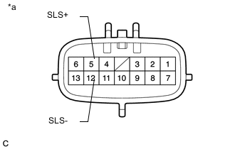
Text in Illustration *a Component without harness connected
(Transmission Wire)
Disconnect the transmission wire connector.
-
Measure the resistance according to the value(s) in the table below.
Standard Resistance Tester Connection Condition Specified Condition 5 (SLS+) - 12 (SLS-) 20°C (68°F) 5.0 to 5.6 Ω 5 (SLS+) - Body ground and other terminals Always 10 kΩ or higher 12 (SLS-) - Body ground and other terminals Always 10 kΩ or higher
NG 
REPLACE CONTINUOUSLY VARIABLE TRANSAXLE ASSEMBLY Click here
OK 
-
-
CHECK HARNESS AND CONNECTOR (TRANSMISSION WIRE - ECM)
-
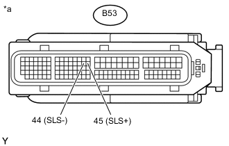
Text in Illustration *a Front view of wire harness connector
(to ECM)
Disconnect the ECM connector.
-
Measure the resistance according to the value(s) in the table below.
Standard Resistance Tester Connection Condition Specified Condition B53-45 (SLS+) - B53-44 (SLS-) 20°C (68°F) 5.0 to 5.6 Ω B53-45 (SLS+) - Body ground and other terminals Always 10 kΩ or higher B53-44 (SLS-) - Body ground and other terminals Always 10 kΩ or higher
NG 
REPAIR OR REPLACE HARNESS OR CONNECTOR (TRANSMISSION WIRE - ECM)
OK
-
-
REPLACE ECM
-
Replace the ECM Click here.
NEXT
PERFORM INITIALIZATION Click here
-
-
REPLACE CONTINUOUSLY VARIABLE TRANSAXLE ASSEMBLY
-
Replace the continuously variable transaxle assembly Click here.
NEXT
PERFORM INITIALIZATION Click here
-