CONTINUOUSLY VARIABLE TRANSAXLE SYSTEM, Diagnostic DTC:P0842, P0843
| DTC Code | DTC Name |
|---|---|
| P0842 | Transmission Fluid Pressure Sensor/Switch "A" Circuit Low |
| P0843 | Transmission Fluid Pressure Sensor/Switch "A" Circuit High |
DESCRIPTION
The ECM performs learning control for the belt clamping pressure based on the belt clamping pressure signal, which is output by the oil pressure sensor.
| DTC Code | DTC Detection Condition
|
Trouble Area |
|---|---|---|
| P0842 |
|
|
| P0843 |
|
|
MONITOR DESCRIPTION
These DTCs indicate an open or short in the oil pressure sensor. If there is an open or short in the oil pressure sensor circuit, the ECM detects the problem and stores the DTC.
WIRING DIAGRAM
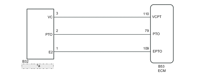
| *a | Oil Pressure Sensor |
CAUTION / NOTICE / HINT
Note
-
Perform initialization when parts related to the continuously variable transaxle are replaced Click here.
-
Check that no DTCs are stored after performing initialization Click here.
PROCEDURE
-
READ VALUE USING GTS (A/T OIL PRESSURE)
CAUTION:
The stall speed test should always be performed with at least 2 people. One person should observe the condition of the wheels and wheel chocks while the other is performing the test.
Note
-
This test must be conducted after checking and confirming that the engine is operating normally.
-
Perform this test while the CVT fluid temperature is between 50 and 100°C (122 and 212°F).
-
Perform this test with the A/C off.
-
Do not perform the stall speed test for longer than 5 seconds.
-
When performing the stall speed test more than once, make sure to wait 15 seconds or more between tests.
-
Warm up the engine.
-
Fully apply the parking brake and chock all 4 wheels.
-
Connect the GTS to the DLC3.
-
Turn the ignition switch to ON.
-
Turn the GTS on.
-
Enter the following menus: Powertrain / Engine and ECT / Active Test / Connect the TC and TE1.
-
Enter the following menus: Powertrain / Engine and ECT / Data List / Primary.
-
In accordance with the display on the GTS, read the Data List.
Engine and ECT Tester Display Measurement Item/Range Normal Condition Diagnostic Note A/T Oil Pressure Secondary oil pressure value/
Min.: -64 MPa
Max.: 63.998 MPa
Secondary oil pressure inspection:
-
4.1 to 5.3 MPa (41.9 to 54.0 kgf/cm2, 594.5 to 768.5 psi): D position stall test
-
4.3 to 5.3 MPa (43.9 to 54.0 kgf/cm2, 623.5 to 768.5 psi): R position stall test
- Result Result Proceed to Data display is not within Normal Condition range A Data display is within Normal Condition range B -
B 
REPLACE ECM Click here
A 
-
-
CHECK HARNESS AND CONNECTOR (OIL PRESSURE SENSOR - ECM)
-
Disconnect the B32 oil pressure sensor connector.
-
Disconnect the B53 ECM connector.
-
Measure the resistance according to the value(s) in the table below.
Standard Resistance Tester Connection Condition Specified Condition B32-1 (E2) - B53-109 (EPTO) Always Below 1 Ω B32-2 (PTO) - B53-79 (PTO) Always Below 1 Ω B32-3 (VC) - B53-110 (VCPT) Always Below 1 Ω B32-1 (E2) or B53-109 (EPTO) - Body ground and other terminals Always 10 kΩ or higher B32-2 (PTO) or B53-79 (PTO) - Body ground and other terminals Always 10 kΩ or higher B32-3 (VC) or B53-110 (VCPT) - Body ground and other terminals Always 10 kΩ or higher -
Measure the voltage according to the value(s) in the table below.
Standard Voltage Tester Connection Switch Condition Specified Condition B53-79 (PTO) - Body ground Ignition switch ON Below 1 V B32-2 (PTO) - Body ground Ignition switch ON Below 1 V
NG 
REPAIR OR REPLACE HARNESS OR CONNECTOR (OIL PRESSURE SENSOR - ECM)
OK
-
-
CHECK ECM (VCPT TERMINAL VOLTAGE)
-
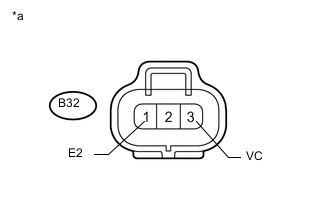
Text in Illustration *a Front view of wire harness connector
(to Oil Pressure Sensor)
Disconnect the oil pressure sensor connector.
-
Measure the voltage according to the value(s) in the table below.
Standard Voltage Tester Connection Switch Condition Specified Condition B32-3 (VC) - B32-1 (E2) Ignition switch ON 4.75 to 5.25 V
NG
REPLACE ECM Click here
OK
-
-
REPLACE OIL PRESSURE SENSOR
-
Replace the oil pressure sensor Click here.
NEXT
PERFORM INITIALIZATION Click here
-
-
REPLACE ECM
-
Replace the ECM Click here.
NEXT
PERFORM INITIALIZATION Click here
-
-
REPLACE ECM
-
Replace the ECM Click here.
NEXT
PERFORM INITIALIZATION Click here
-