CONTINUOUSLY VARIABLE TRANSAXLE SYSTEM, Diagnostic DTC:P1585
| DTC Code | DTC Name |
|---|---|
| P1585 | Acceleration Sensor Circuit |
DESCRIPTION
The ECM determines the vehicle inclination based on a signal from the yaw rate sensor.
Tech Tips
If a CAN communication DTC is output, perform troubleshooting for that DTC first.
| DTC Code | DTC Detection Condition
|
Trouble Area |
|---|---|---|
| P1585 |
|
|
|
||
|
||
|
||
|
WIRING DIAGRAM
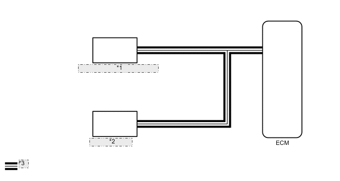
| *1 | Brake Actuator Assembly (Skid Control ECU) |
| *2 | Yaw Rate Sensor |
| *3 | CAN Communication Line |
PROCEDURE
-
CHECK DTC OUTPUT (CAN COMMUNICATION SYSTEM)
-
Check for DTCs of the CAN communication system Click here.
Result Result Proceed to DTCs are not output A DTCs are output B
B 
GO TO CAN COMMUNICATION SYSTEM (HOW TO PROCEED WITH TROUBLESHOOTING) Click here
A 
-
-
READ VALUE USING INTELLIGENT TESTER (G SENSOR)
-
Connect the intelligent tester to the DLC3.
-
Turn the ignition switch to ON.
-
Turn the intelligent tester on.
-
Enter the following menus: Powertrain / Engine and ECT / Data List.
-
In accordance with the display on the tester, read the Data List.
Engine and ECT Tester Display Measurement Item/Range Normal Condition Diagnostic Note G sensor Converted output voltage of yaw rate sensor/
min.: 0 V
max.: 5 V
Displays converted voltage of yaw rate sensor
-
Vehicle on level ground: 2.31 V to 2.69 V
-
Decelerating: 1.88 V to 2.5 V
-
Accelerating: 2.5 V to 3.11 V
-
G sensor malfunction: Set to 1.87 V
-
Communication malfunction: Set to 1.87 V
- Result Result Proceed to Data displayed is not as specified under Normal Condition A Data displayed is as specified under Normal Condition B -
B
REPLACE BRAKE ACTUATOR ASSEMBLY (SKID CONTROL ECU) Click here
A
-
-
REPLACE YAW RATE SENSOR
-
Replace the yaw rate sensor Click here.
NEXT
-
-
PERFORM INITIALIZATION
Note
-
Performing reset memory will clear the learned values of both the yaw rate sensor (deceleration sensor 0 point calibration) and CVT oil pressure (CVT oil pressure calibration). Make sure to perform reset memory, yaw rate sensor 0 point calibration and CVT oil pressure calibration when replacing any of the parts shown in the following table:
Replaced Part
-
Continuously variable transaxle assembly
-
ECM
-
Oil pressure sensor
-
Yaw rate sensor
-
-
After performing reset memory, always perform yaw rate sensor (deceleration sensor 0 point) calibration first, and then CVT oil pressure calibration.
-
Always perform 0 point calibration with the vehicle on level ground (Inclination: 0 +/-0.25°).
-
Do not shake or vibrate the vehicle during 0 point calibration.
-
Using the intelligent tester, perform reset memory, deceleration sensor 0 point calibration and CVT oil pressure calibration Click here.
-
Check that no DTC is stored.
NEXT
END
-