TRANSMISSION CONTROL CABLE INSTALLATION
CAUTION / NOTICE / HINT
Tech Tips
-
Use the same procedure for RHD and LHD vehicles.
-
The procedure listed below is for LHD vehicles.
PROCEDURE
-
INSTALL TRANSMISSION CONTROL CABLE ASSEMBLY
-
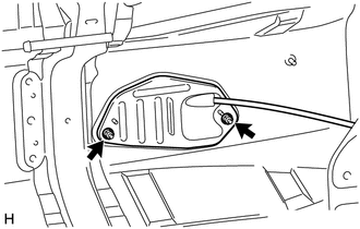
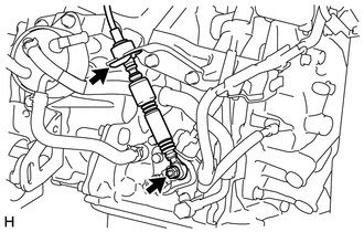
Install the transmission control cable assembly to the body with the 2 bolts.
- Torque:
- 5.0 N*m { 51 kgf*cm, 44 in.*lbf }
-
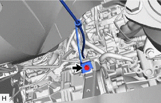
Install the transmission control cable assembly to rear engine mounting insulator with the bolt.
- Torque:
- 5.0 N*m { 51 kgf*cm, 44 in.*lbf }
-
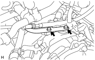
Install the transmission control cable assembly to the transmission control cable support with the 2 bolts.
- Torque:
- 5.0 N*m { 51 kgf*cm, 44 in.*lbf }
-
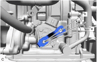
Text in Illustration *a P Position *b N Position Turn the control shaft lever clockwise until it stops, then turn it counterclockwise 2 notches.
-
Install the transmission control cable assembly to the No. 1 transmission control cable bracket with a new clip.
-
Install the transmission control cable assembly to the control shaft lever with the nut.
- Torque:
- 12 N*m { 122 kgf*cm, 9 ft.*lbf }
-
-
CONNECT TRANSMISSION CONTROL CABLE ASSEMBLY
-
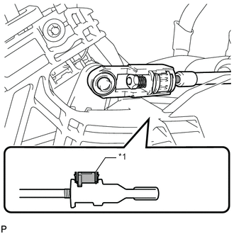
Turn the nut of the transmission control cable 180° counterclockwise. While holding the nut in place, push in the stopper until the stopper clicks twice.
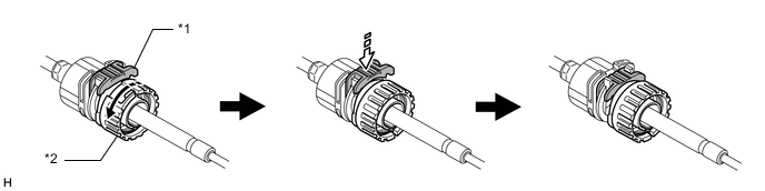
Text in Illustration *1 Stopper *2 Nut 
Turn in this Direction 
Push in this Direction -
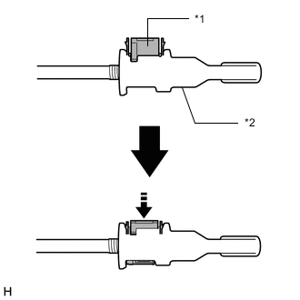
Install the outer part of the transmission control cable to the shift lever assembly. Check that the spring is positioned at "A" and push in the stopper.
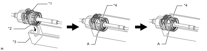
Text in Illustration *1 Stopper *2 Nut *3 Shift Lever Assembly *4 Spring Install in this Direction - - Tech Tips
If the stopper cannot be pushed in, slightly turn the nut clockwise and then push in the stopper again.
-
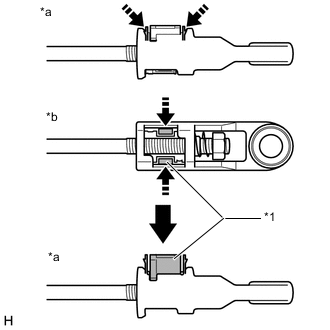
Text in Illustration *1 Transmission Control Cable Lock Piece *a Side View *b Bottom View Push in this Direction Push the 2 claws together at the top of the transmission control cable lock piece. While holding the 2 claws together, push the 2 lugs on the bottom of the transmission control cable lock piece toward each other and upward to pull out the transmission control cable lock piece.
-
Text in Illustration *1 Transmission Control Cable Lock Piece Connect the end of the cable to the shift lever assembly.
Note
-
Make sure that the transmission control cable lock piece is pulled up.
-
Push on the end of the cable all the way to the base of the pin.
-
-
Text in Illustration *1 Transmission Control Cable Lock Piece *1 Adjuster Case Push in this Direction Push the transmission control cable lock piece into the adjuster case.
Note
Securely push in the transmission control cable lock piece until it locks.
-
-
INSPECT SHIFT LEVER POSITION
-
ADJUST SHIFT LEVER POSITION
-
INSTALL REAR CONSOLE BOX ASSEMBLY
-
INSTALL FRONT FLOOR NO. 1 HEAT INSULATOR
-
INSTALL FRONT EXHAUST PIPE ASSEMBLY
-
CONNECT HEATED OXYGEN SENSOR CONNECTOR
-
INSTALL NO. 2 ENGINE UNDER COVER
-
INSTALL REAR ENGINE UNDER COVER LH
-
INSTALL NO. 1 ENGINE UNDER COVER
-
INSTALL BATTERY CARRIER
-
CONNECT RADIATOR PIPE
-
INSTALL BATTERY TRAY
-
INSTALL BATTERY
-
INSTALL BATTERY CLAMP SUB-ASSEMBLY
-
INSTALL AIR CLEANER CASE SUB-ASSEMBLY
-
INSTALL AIR CLEANER FILTER ELEMENT SUB-ASSEMBLY
-
Install the air cleaner filter element sub-assembly to the air cleaner case sub-assembly.
-
-
INSTALL AIR CLEANER CAP SUB-ASSEMBLY
-
INSTALL RADIATOR SUPPORT OPENING COVER
-
INSTALL NO. 2 CYLINDER HEAD COVER
-
CONNECT CABLE TO POSITIVE BATTERY TERMINAL
-
CONNECT CABLE TO NEGATIVE BATTERY TERMINAL
Note
When disconnecting the cable, some systems need to be initialized after the cable is reconnected Click here.