FRONT POWER SEAT CONTROL SYSTEM, Diagnostic DTC:B2658
| DTC Code | DTC Name |
|---|---|
| B2658 | Short in Sensor with Motor Power Supply Circuit |
DESCRIPTION
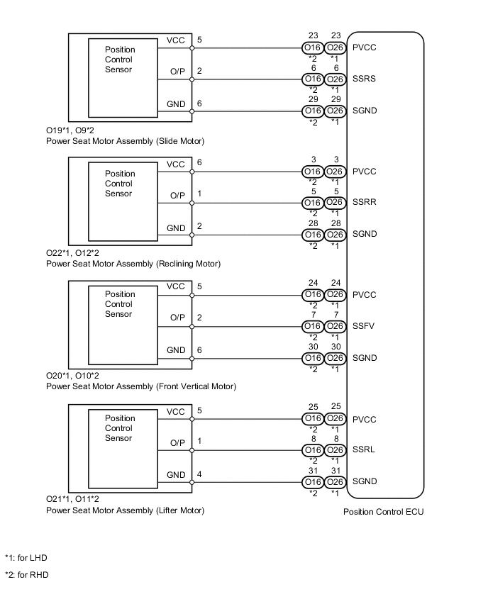
This DTC is stored when a power seat motor operates (a position control sensor is being supplied with power) and the power supply voltage does not rise to the specified value.
| DTC Code | DTC Detection Condition | Trouble Area |
|---|---|---|
| B2658 | Problem with voltage supplied to the position control sensor. |
|
WIRING DIAGRAM
PROCEDURE
-
CHECK FOR DTC
-
Clear the DTCs Click here.
-
Check for DTCs Click here.
OK DTC B2658 output does not occur.
OK 
USE SIMULATION METHOD TO CHECK Click here
NG 
-
-
CHECK HARNESS AND CONNECTOR (POSITION CONTROL ECU - POWER SEAT MOTOR [SLIDE MOTOR])
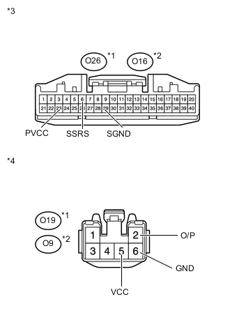
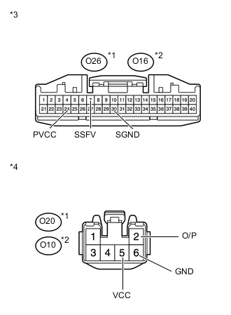
Text in Illustration *1 for LHD *2 for RHD *3 Front view of wire harness connector
(to Position Control ECU)
*4 Front view of wire harness connector
(to Power Seat Motor)
-
*1: for LHD
-
*2: for RHD
-
Disconnect the O26*1 or O16*2 ECU connector.
-
Disconnect the O19*1 or O9*2 motor connector.
-
Measure the resistance according to the value(s) in the table below.
Standard Resistance for LHD Tester Connection Condition Specified Condition O26-23 (PVCC) - O19-5 (VCC) Always Below 1 Ω O26-6 (SSRS) - O19-2 (O/P) Always Below 1 Ω O26-29 (SGND) - O19-6 (GND) Always Below 1 Ω O26-23 (PVCC) - Body ground Always 10 kΩ or higher O26-6 (SSRS) - Body ground Always 10 kΩ or higher O26-29 (SGND) - Body ground Always 10 kΩ or higher for RHD Tester Connection Condition Specified Condition O16-23 (PVCC) - O9-5 (VCC) Always Below 1 Ω O16-6 (SSRS) - O9-2 (O/P) Always Below 1 Ω O16-29 (SGND) - O9-6 (GND) Always Below 1 Ω O16-23 (PVCC) - Body ground Always 10 kΩ or higher O16-6 (SSRS) - Body ground Always 10 kΩ or higher O16-29 (SGND) - Body ground Always 10 kΩ or higher
NG
REPAIR OR REPLACE HARNESS OR CONNECTOR
OK
-
-
CHECK POSITION CONTROL ECU ASSEMBLY

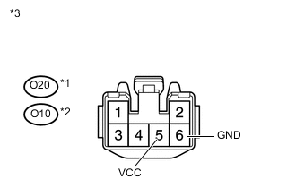
Text in Illustration *1 for LHD *2 for RHD *3 Front view of wire harness connector
(to Power Seat Motor)
-
Disconnect the O19*1 or O9*2 motor connector.
-
*1: for LHD
-
*2: for RHD
-
-
Measure the voltage according to the value(s) in the table below.
Standard Voltage for LHD Tester Connection Switch Condition Specified Condition O19-5 (VCC) - O19-6 (GND) Sliding switch on 5.5 to 6.5 V for RHD Tester Connection Switch Condition Specified Condition O9-5 (VCC) - O9-6 (GND) Sliding switch on 5.5 to 6.5 V
NG
REPLACE POSITION CONTROL ECU ASSEMBLY Click here
OK
-
-
CHECK HARNESS AND CONNECTOR (POSITION CONTROL ECU - POWER SEAT MOTOR [RECLINING MOTOR])
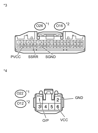
Text in Illustration *1 for LHD *2 for RHD *3 Front view of wire harness connector
(to Position Control ECU)
*4 Front view of wire harness connector
(to Power Seat Motor)
-
*1: for LHD
-
*2: for RHD
-
Disconnect the O26*1 or O16*2 ECU connector.
-
Disconnect the O22*1 or O12*2 motor connector.
-
Measure the resistance according to the value(s) in the table below.
Standard Resistance for LHD Tester Connection Condition Specified Condition O26-3 (PVCC) - O22-6 (VCC) Always Below 1 Ω O26-5 (SSRR) - O22-1 (O/P) Always Below 1 Ω O26-28 (SGND) - O22-2 (GND) Always Below 1 Ω O26-3 (PVCC) - Body ground Always 10 kΩ or higher O26-5 (SSRR) - Body ground Always 10 kΩ or higher O26-28 (SGND) - Body ground Always 10 kΩ or higher for RHD Tester Connection Condition Specified Condition O16-3 (PVCC) - O12-6 (VCC) Always Below 1 Ω O16-5 (SSRR) - O12-1 (O/P) Always Below 1 Ω O16-28 (SGND) - O12-2 (GND) Always Below 1 Ω O16-3 (PVCC) - Body ground Always 10 kΩ or higher O16-5 (SSRR) - Body ground Always 10 kΩ or higher O16-28 (SGND) - Body ground Always 10 kΩ or higher
NG
REPAIR OR REPLACE HARNESS OR CONNECTOR
OK
-
-
CHECK POSITION CONTROL ECU ASSEMBLY
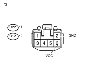
Text in Illustration *1 for LHD *2 for RHD *3 Front view of wire harness connector
(to Power Seat Motor)
-
Disconnect the O22*1 or O12*2 motor connector.
-
*1: for LHD
-
*2: for RHD
-
-
Measure the voltage according to the value(s) in the table below.
Standard Voltage for LHD Tester Connection Switch Condition Specified Condition O22-6 (VCC) - O22-2 (GND) Reclining switch on 5.5 to 6.5 V for RHD Tester Connection Switch Condition Specified Condition O12-6 (VCC) - O12-2 (GND) Reclining switch on 5.5 to 6.5 V
NG
REPLACE POSITION CONTROL ECU ASSEMBLY Click here
OK
-
-
CHECK HARNESS AND CONNECTOR (POSITION CONTROL ECU - POWER SEAT MOTOR [FRONT VERTICAL MOTOR])
Text in Illustration *1 for LHD *2 for RHD *3 Front view of wire harness connector
(to Position Control ECU)
*4 Front view of wire harness connector
(to Power Seat Motor)
-
*1: for LHD
-
*2: for RHD
-
Disconnect the O26*1 or O16*2 ECU connector.
-
Disconnect the O20*1 or O10*2 motor connector.
-
Measure the resistance according to the value(s) in the table below.
Standard Resistance for LHD Tester Connection Condition Specified Condition O26-24 (PVCC) - O20-5 (VCC) Always Below 1 Ω O26-7 (SSFV) - O20-2 (O/P) Always Below 1 Ω O26-30 (SGND) - O20-6 (GND) Always Below 1 Ω O26-24 (PVCC) - Body ground Always 10 kΩ or higher O26-7 (SSFV) - Body ground Always 10 kΩ or higher O26-30 (SGND) - Body ground Always 10 kΩ or higher for RHD Tester Connection Condition Specified Condition O16-24 (PVCC) - O10-5 (VCC) Always Below 1 Ω O16-7 (SSFV) - O10-2 (O/P) Always Below 1 Ω O16-30 (SGND) - O10-6 (GND) Always Below 1 Ω O16-24 (PVCC) - Body ground Always 10 kΩ or higher O16-7 (SSFV) - Body ground Always 10 kΩ or higher O16-30 (SGND) - Body ground Always 10 kΩ or higher
NG
REPAIR OR REPLACE HARNESS OR CONNECTOR
OK
-
-
CHECK POSITION CONTROL ECU ASSEMBLY
Text in Illustration *1 for LHD *2 for RHD *3 Front view of wire harness connector
(to Power Seat Motor)
-
Disconnect the O20*1 or O10*2 motor connector.
-
*1: for LHD
-
*2: for RHD
-
-
Measure the voltage according to the value(s) in the table below.
Standard Voltage for LHD Tester Connection Switch Condition Specified Condition O20-5 (VCC) - O20-6 (GND) Front vertical switch on 5.5 to 6.5 V for RHD Tester Connection Switch Condition Specified Condition O10-5 (VCC) - O10-6 (GND) Front vertical switch on 5.5 to 6.5 V
NG
REPLACE POSITION CONTROL ECU ASSEMBLY Click here
OK
-
-
CHECK HARNESS AND CONNECTOR (POSITION CONTROL ECU - POWER SEAT MOTOR [LIFTER MOTOR])
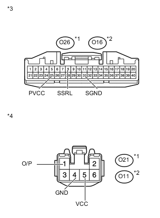
Text in Illustration *1 for LHD *2 for RHD *3 Front view of wire harness connector
(to Position Control ECU)
*4 Front view of wire harness connector
(to Power Seat Motor)
-
*1: for LHD
-
*2: for RHD
-
Disconnect the O26*1 or O16*2 ECU connector.
-
Disconnect the O21*1 or O11*2 motor connector.
-
Measure the resistance according to the value(s) in the table below.
Standard Resistance for LHD Tester Connection Condition Specified Condition O26-25 (PVCC) - O21-5 (VCC) Always Below 1 Ω O26-8 (SSRL) - O21-1 (O/P) Always Below 1 Ω O26-31 (SGND) - O21-4 (GND) Always Below 1 Ω O26-25 (PVCC) - Body ground Always 10 kΩ or higher O26-8 (SSRL) - Body ground Always 10 kΩ or higher O26-31 (SGND) - Body ground Always 10 kΩ or higher for RHD Tester Connection Condition Specified Condition O16-25 (PVCC) - O11-5 (VCC) Always Below 1 Ω O16-8 (SSRL) - O11-1 (O/P) Always Below 1 Ω O16-31 (SGND) - O11-4 (GND) Always Below 1 Ω O16-25 (PVCC) - Body ground Always 10 kΩ or higher O16-8 (SSRL) - Body ground Always 10 kΩ or higher O16-31 (SGND) - Body ground Always 10 kΩ or higher
NG
REPAIR OR REPLACE HARNESS OR CONNECTOR
OK
-
-
CHECK POSITION CONTROL ECU ASSEMBLY
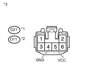
Text in Illustration *1 for LHD *2 for RHD *3 Front view of wire harness connector
(to Power Seat Motor)
-
Disconnect the O21*1 or O11*2 motor connector.
-
*1: for LHD
-
*2: for RHD
-
-
Measure the voltage according to the value(s) in the table below.
Standard Voltage for LHD Tester Connection Switch Condition Specified Condition O21-5 (VCC) - O21-4 (GND) Lifter switch on 5.5 to 6.5 V for RHD Tester Connection Switch Condition Specified Condition O11-5 (VCC) - O11-4 (GND) Lifter switch on 5.5 to 6.5 V
NG
REPLACE POSITION CONTROL ECU ASSEMBLY Click here
OK
-
-
CHECK POWER SEAT MOTOR ASSEMBLY (OPERATION)
-
Clear the DTCs Click here.
-
Temporarily replace each power seat motor one at a time with a new or normally functioning one.
-
Slide motor.
-
Reclining motor Click here.
-
Front vertical motor Click here.
-
Lifter motor Click here.
-
-
Check for DTCs Click here.
OK DTC B2658 output does not occur. Result Result Proceed to NG A OK (Slide motor) B OK (Reclining motor) C OK (Front vertical motor) D OK (Lifter motor) E
A
REPLACE POSITION CONTROL ECU ASSEMBLY Click here
B
END (REPLACE POWER SEAT MOTOR ASSEMBLY [SLIDE MOTOR])
C
END (REPLACE POWER SEAT MOTOR ASSEMBLY [RECLINING MOTOR]) Click here
D
END (REPLACE POWER SEAT MOTOR ASSEMBLY [FRONT VERTICAL MOTOR]) Click here
E
END (REPLACE POWER SEAT MOTOR ASSEMBLY [LIFTER MOTOR]) Click here
-