SEAT HEATER CONTROL(for Power Seat) INSPECTION
PROCEDURE
-
INSPECT SEAT CLIMATE CONTROL CONTROLLER LH
-
Before inspecting the seat climate control controller LH, check the continuity between the following connectors of the front seat cushion heater LH. After confirming that there are no abnormalities, inspect the seat climate control controller LH.
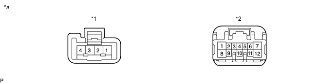
*1 Connector A *2 Connector B *a Component without harness connected
(Front Seat Cushion Heater Assembly LH)
- - Standard Resistance Tester Connection Condition Specified Condition A1 - B12 Always Below 1 Ω A2 - B4 A3 - B3 A4 - B8 If the result is not as specified, replace the front seat cushion heater LH, and then inspect the seat climate control controller LH again.
-
Disconnect the seat climate control controller LH connectors.
-
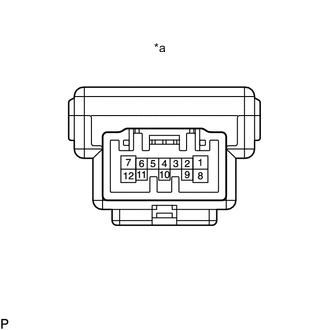
*a Component without harness connected
(Seat Climate Control Controller LH)
Measure the resistance according to the value(s) in the table below.
Standard Resistance Tester Connection Condition Specified Condition 7 - 12 Always Below 1 Ω If the result is not as specified, replace the seat climate control controller LH.
-
Disconnect the front seat cushion heater assembly LH connector.
-
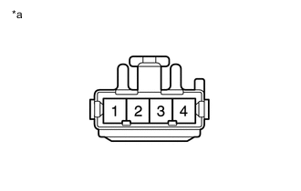
*a Front view of wire harness connector
(to Front Seat Cushion Heater Assembly LH)
Measure the voltage and resistance according to the value(s) in the table below.
Standard Resistance Tester Connection Condition Specified Condition 1 - Body ground Always Below 1 Ω Standard Voltage Tester Connection Switch Condition Specified Condition 1 - 4 Ignition switch ON 11 to 14 V 2 - 4 Ignition switch ON, seat heater switch min. → max. Gradual increase from below 1 V to 11 to 14 V 3 - 4 Ignition switch ON, seat heater switch off → on Below 1 V → 11 to 14 V If the result is not as specified, repair or replace the wire harness or connector LH.
-
Connect the seat climate control controller LH and front seat cushion heater assembly LH connectors.
-
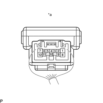
*a Component with harness connected
(Seat Climate Control Controller LH)
Measure the voltage according to the value(s) in the table below.
Standard Voltage Tester Connection Switch Condition Specified Condition 1 - 12 Ignition switch ON, seat heater switch min. → max. 11 to 14 V If the result is not as specified, replace the seat climate control controller LH.
-
-
INSPECT SEAT CLIMATE CONTROL CONTROLLER RH
-
Before inspecting the seat climate control controller RH, check the continuity between the following connectors of the front seat cushion heater RH. After confirming that there are no abnormalities, inspect the seat climate control controller RH.
*1 Connector A *2 Connector B *a Component without harness connected
(Front Seat Cushion Heater Assembly RH)
- - Standard Resistance Tester Connection Condition Specified Condition A1 - B12 Always Below 1 Ω A2 - B4 A3 - B3 A4 - B8 If the result is not as specified, replace the front seat cushion heater RH, and then inspect the seat climate control controller RH again.
-
Disconnect the seat climate control controller RH connectors.
-
*a Component without harness connected
(Seat Climate Control Controller RH)
Measure the resistance according to the value(s) in the table below.
Standard Resistance Tester Connection Condition Specified Condition 7 - 12 Always Below 1 Ω If the result is not as specified, replace the seat climate control controller RH.
-
Disconnect the front seat cushion heater assembly RH connector.
-
*a Front view of wire harness connector
(to Front Seat Cushion Heater Assembly RH)
Measure the voltage and resistance according to the value(s) in the table below.
Standard Resistance Tester Connection Condition Specified Condition 1 - Body ground Always Below 1 Ω Standard Voltage Tester Connection Switch Condition Specified Condition 1 - 4 Ignition switch ON 11 to 14 V 2 - 4 Ignition switch ON, seat heater switch min. → max. Gradual increase from below 1 V to 11 to 14 V 3 - 4 Ignition switch ON, seat heater switch off → on Below 1 V → 11 to 14 V If the result is not as specified, repair or replace the wire harness or connector RH.
-
Connect the seat climate control controller RH and front seat cushion heater assembly RH connectors.
-
*a Component with harness connected
(Seat Climate Control Controller RH)
Measure the voltage according to the value(s) in the table below.
Standard Voltage Tester Connection Switch Condition Specified Condition 1 - 12 Ignition switch ON, seat heater switch min. → max. 11 to 14 V If the result is not as specified, replace the seat climate control controller RH.
-