OIL PUMP REMOVAL

PROCEDURE
-
REMOVE ENGINE ASSEMBLY WITH TRANSAXLE
-
Remove the engine assembly with transaxle Click here.
-
-
REMOVE ENGINE OIL LEVEL DIPSTICK GUIDE
-
DISCONNECT NO. 3 WATER BY-PASS HOSE
-
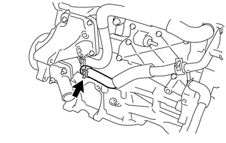
Disconnect the No. 3 water by-pass hose from the water inlet housing.
-
-
DISCONNECT WATER INLET HOSE
-
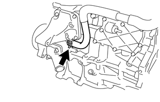
Disconnect the water inlet hose from the water inlet housing.
-
-
REMOVE WATER INLET
-
REMOVE THERMOSTAT
-
REMOVE IGNITION COIL ASSEMBLY
-
REMOVE RADIO SETTING CONDENSER
-
REMOVE CYLINDER HEAD COVER SUB-ASSEMBLY
-
REMOVE CYLINDER HEAD COVER GASKET
-
REMOVE SPARK PLUG TUBE GASKET
-
SET NO. 1 CYLINDER TO TDC/COMPRESSION
-
REMOVE CRANKSHAFT PULLEY
-
REMOVE NO. 1 CHAIN TENSIONER ASSEMBLY
-
REMOVE TIMING CHAIN COVER SUB-ASSEMBLY
-
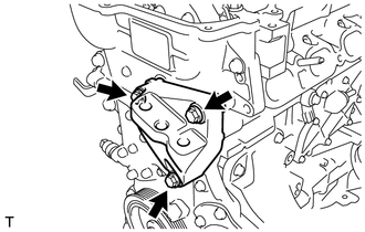
Remove the 3 bolts and engine mounting bracket.
-
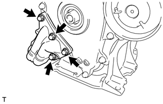
Remove the 4 bolts and oil filter bracket.
-
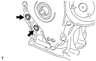
Remove the 2 O-rings.
-
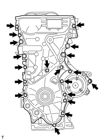
Remove the 19 bolts.
-
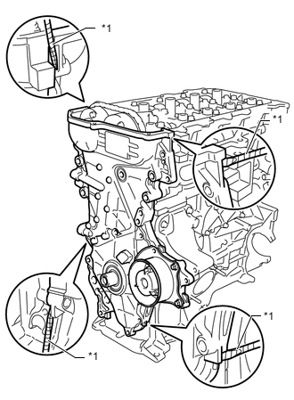
Text in Illustration *1 Protective Tape Remove the timing chain cover by prying between the timing chain cover and cylinder head, camshaft housing, cylinder block and stiffening crankcase with a screwdriver as shown in the illustration.
Tech Tips
Tape the screwdriver tip before use.
Note
Be careful not to damage the contact surfaces of the cylinder head, camshaft housing, cylinder block, stiffening crankcase and timing chain cover.
-
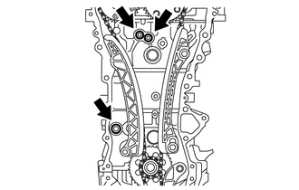
Remove the 3 O-rings.
-
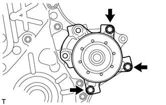
Remove the 3 bolts and water pump.
-
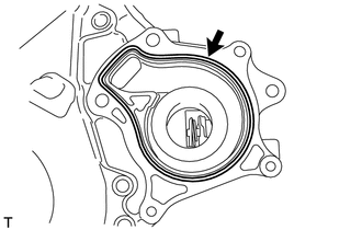
Remove the gasket.
-
-
REMOVE TIMING CHAIN COVER OIL SEAL
-
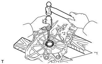
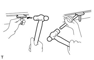
Text in Illustration *1 Wooden Block *2 Protective Tape Place the timing chain cover on wooden blocks.
-
Using a screwdriver, tap out the oil seal.
Tech Tips
Tape the screwdriver tip before use.
Note
Do not damage the surface of the oil seal press fit hole.
-
-
REMOVE CHAIN TENSIONER SLIPPER
-
REMOVE NO. 1 CHAIN VIBRATION DAMPER
-
REMOVE CHAIN SUB-ASSEMBLY
-
REMOVE CRANKSHAFT TIMING SPROCKET
-
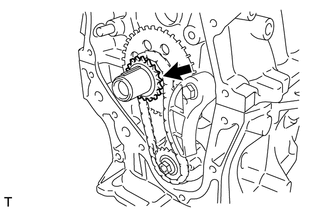
Remove the crankshaft timing sprocket.
-
-
REMOVE NO. 2 CHAIN SUB-ASSEMBLY
-
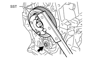
Temporarily install the crankshaft pulley and crankshaft pulley bolt.
-
Using SST, hold the crankshaft. Then remove the drive shaft gear nut.
for 86 mm (3.39 in.) Bolt Pitch Type:
- SST
- 09213-58014 ( 91551-80840 )
- 09330-00021
for 64 mm (2.52 in.) Bolt Pitch Type:
- SST
- 09213-54015
- 09330-00021
Tech Tips
For the 64 mm (2.52 in.) bolt pitch type, the part number of the installation bolt for SST (crankshaft pulley holding tool) is 91551-00850 (quantity: 2).
-
Remove SST, the crankshaft pulley bolt and crankshaft pulley.
-
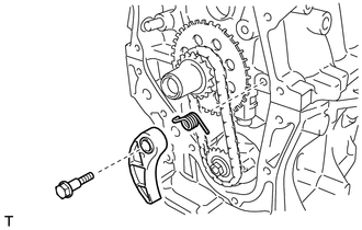
Remove the bolt, chain tensioner plate and spring.
-
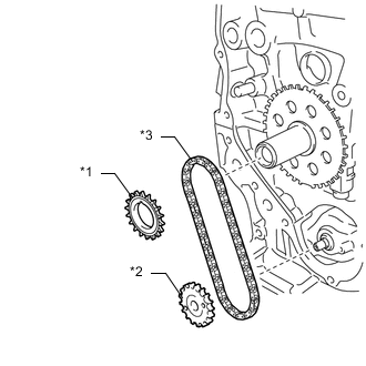
Text in Illustration *1 Oil Pump Dive Gear *2 Oil Pump Drive Shaft Gear *3 No. 2 Chain Sub-Assembly Remove the oil pump drive gear, oil pump drive shaft gear and No. 2 chain.
-
-
REMOVE NO. 2 OIL PAN SUB-ASSEMBLY
-
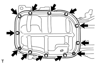
Remove the 10 bolts and 2 nuts.
-
Insert the blade of an oil pan seal cutter between the crankcase and oil pan. Cut through the sealer and remove the oil pan.
Note
-
Be careful not to damage the surface of the oil pan which contacts the stiffening crankcase.
-
Be careful not to damage the stiffening crankcase flange.
-
-
-
REMOVE OIL PUMP ASSEMBLY
-
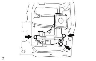
Remove the 3 bolts and oil pump.
-