COOLING FAN SYSTEM Cooling Fan Circuit
DESCRIPTION
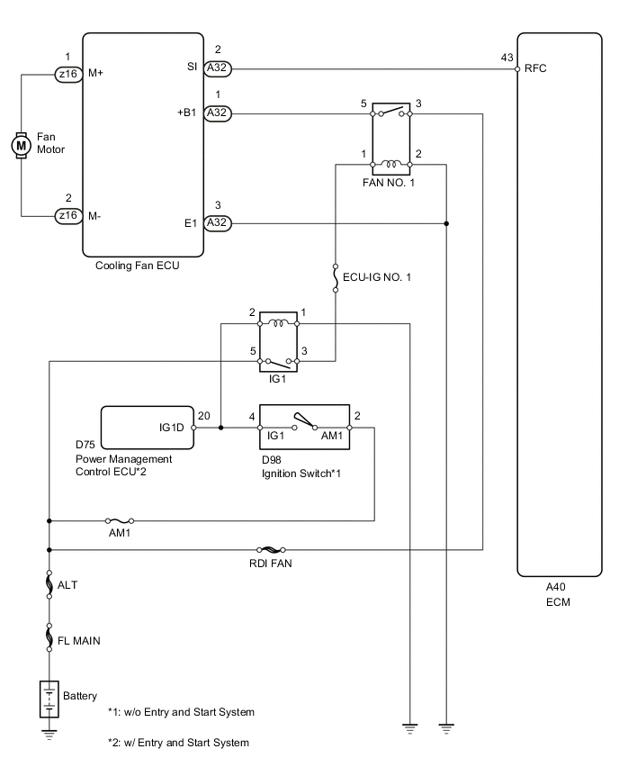
The ECM calculates an appropriate cooling fan speed based on the engine coolant temperature, air conditioning switch condition, refrigerant pressure, engine speed and vehicle speed, and sends signals to the cooling fan ECU to regulate the cooling fan. The cooling fan ECU controls the cooling fan speed based on the duty ratio signal sent from the ECM.
WIRING DIAGRAM
CAUTION / NOTICE / HINT
Note
Inspect the fuses for circuits related to this system before performing the following inspection procedure.
PROCEDURE
-
PERFORM ACTIVE TEST USING INTELLIGENT TESTER (CONTROL THE ELECTRIC COOLING FAN)
-
Connect the intelligent tester to the DLC3.
-
Turn the ignition switch to ON.
-
Enter the following menus: Powertrain / Engine and ECT / Active Test / Control the Electric Cooling Fan.
-
Check the operation of the cooling fan while operating it using the intelligent tester.
OK Tester Operation Fan Operation ON Cooling fan operates OFF Cooling fan stops Result Result Proceed to OK A Cooling fan does not operate B Cooling fan does not stop C
A 
PROCEED TO NEXT SUSPECTED AREA SHOWN IN PROBLEM SYMPTOMS TABLE Click here
C 
CHECK HARNESS AND CONNECTOR (ECM - COOLING FAN ECU) Click here
B 
-
-
CHECK COOLING FAN SYSTEM
-
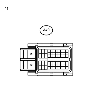
Text in Illustration *1 Front view of wire harness connector
(to ECM)
Disconnect the A40 ECM connector.
-
Turn the ignition switch to ON.
-
Check the operation of the cooling fan.
OK The cooling fan operates. -
Reconnect the ECM connector.
OK
REPLACE ECM Click here
NG
-
-
CHECK HARNESS AND CONNECTOR (ECM - COOLING FAN ECU)
-
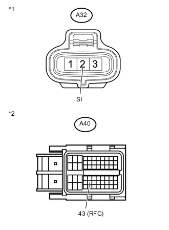
Text in Illustration *1 Front view of wire harness connector
(to Cooling Fan ECU)
*2 Front view of wire harness connector
(to ECM)
Disconnect the cooling fan ECU connector.
-
Disconnect the ECM connector.
-
Measure the resistance according to the value(s) in the table below.
Standard Resistance (Check for Open) Tester Connection Condition Specified Condition A40-43 (RFC) - A32-2 (SI) Always Below 1 Ω Standard Resistance (Check for Short) Tester Connection Condition Specified Condition A40-43 (RFC) or A32-2 (SI) - Body ground Always 10 kΩ or higher -
Reconnect the cooling fan ECU connector.
-
Reconnect the ECM connector.
NG
REPAIR OR REPLACE HARNESS OR CONNECTOR (ECM - COOLING FAN ECU)
OK
-
-
INSPECT COOLING FAN MOTOR
-
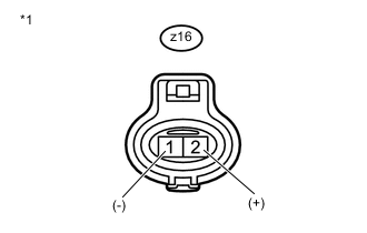
Text in Illustration *1 Component without harness connected
(Cooling Fan Motor)
Disconnect the cooling fan motor connector.
-
Apply 12 V battery voltage to the cooling fan motor and check that the cooling fan operates.
OK Measurement Condition Specified Condition
-
Battery positive (+) → Terminal 2
-
Battery negative (-) → Terminal 1
Cooling fan operates -
-
Reconnect the cooling fan motor connector.
NG
REPLACE COOLING FAN MOTOR Click here
OK
-
-
CHECK COOLING FAN ECU (POWER SOURCE)
-
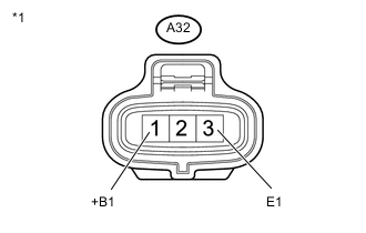
Text in Illustration *1 Front view of wire harness connector
(to Cooling Fan ECU)
Disconnect the cooling fan ECU connector.
-
Turn the ignition switch to ON.
-
Measure the voltage according to the value(s) in the table below.
Standard Voltage Tester Connection Switch Condition Specified Condition A32-1 (+B1) - A32-3 (E1) Ignition switch ON 11 to 14 V -
Reconnect the cooling fan ECU connector.
OK
REPLACE COOLING FAN ECU
NG
-
-
CHECK HARNESS AND CONNECTOR (COOLING FAN ECU - BODY GROUND)
-
Disconnect the cooling fan ECU connector.
-
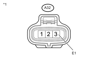
Text in Illustration *1 Front view of wire harness connector
(to Cooling Fan ECU)
Measure the resistance according to the value(s) in the table below.
Standard Resistance Tester Connection Condition Specified Condition A32-3 (E1) - Body ground Always Below 1 Ω -
Reconnect the cooling fan ECU connector.
NG
REPAIR OR REPLACE HARNESS OR CONNECTOR (COOLING FAN ECU - BODY GROUND)
OK
-
-
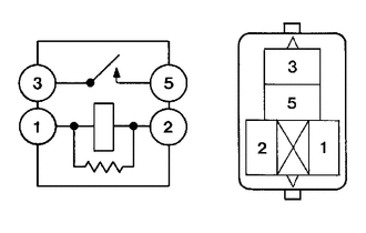
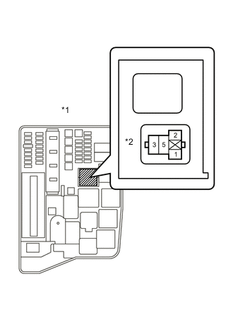
INSPECT FAN NO. 1 RELAY
-
Remove the FAN NO. 1 relay from the engine room No. 1 relay block.
-
Measure the resistance according to the value(s) in the table below.
Standard Resistance Tester Connection Condition Specified Condition 3 - 5 No battery voltage applied to terminals 1 and 2 10 kΩ or higher 3 - 5 Battery voltage applied to terminals 1 and 2 Below 1 Ω -
Reinstall the FAN NO. 1 relay.
NG
REPLACE FAN NO. 1 RELAY
OK
-
-
CHECK HARNESS AND CONNECTOR (COOLING FAN ECU - FAN NO. 1 RELAY)
-
Disconnect the cooling fan ECU connector.
-
Remove the FAN NO. 1 relay from the engine room No. 1 relay block.
-
Measure the resistance according to the value(s) in the table below.
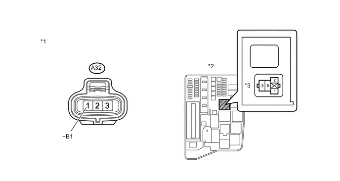
Standard Resistance (Check for Open) Tester Connection Condition Specified Condition A32-1 (+B1) - Relay block FAN NO. 1 relay terminal (5) Always Below 1 Ω Standard Resistance (Check for Short) Tester Connection Condition Specified Condition A32-1 (+B1) or Relay block FAN NO. 1 relay terminal (5) - Body ground Always 10 kΩ or higher Text in Illustration *1 Front view of wire harness connector
(to Cooling Fan ECU)
*2 Engine Room No. 1 Relay Block *3 Relay Block FAN NO. 1 Relay Terminals -
Reinstall the FAN NO. 1 relay.
-
Reconnect the cooling fan ECU connector.
NG
REPAIR OR REPLACE HARNESS OR CONNECTOR (COOLING FAN ECU - FAN NO. 1 RELAY)
OK
-
-
CHECK HARNESS AND CONNECTOR (FAN NO. 1 RELAY - BODY GROUND)
-
Text in Illustration *1 Engine Room No. 1 Relay Block *2 Relay Block FAN NO. 1 Relay Terminals Remove the FAN NO. 1 relay from the engine room No. 1 relay block.
-
Measure the resistance according to the value(s) in the table below.
Standard Resistance Tester Connection Condition Specified Condition Relay block FAN NO. 1 relay terminal (2) - Body ground Always Below 1 Ω -
Reinstall the FAN NO. 1 relay.
NG
REPAIR OR REPLACE HARNESS OR CONNECTOR (FAN NO. 1 RELAY - BODY GROUND)
OK
-
-
CHECK HARNESS AND CONNECTOR (FAN NO. 1 RELAY - BATTERY)
-
Text in Illustration *1 Engine Room No. 1 Relay Block *2 Relay Block FAN NO. 1 Relay Terminals Remove the FAN NO. 1 relay from the engine room No. 1 relay block.
-
Measure the voltage according to the value(s) in the table below.
Standard Voltage Tester Connection Condition Specified Condition Relay block FAN NO. 1 relay terminal (3) - Body ground Always 11 to 14 V -
Reinstall the FAN NO. 1 relay.
OK
REPAIR OR REPLACE HARNESS OR CONNECTOR (FAN NO. 1 RELAY - IG1 RELAY)
NG
REPAIR OR REPLACE HARNESS OR CONNECTOR (FAN NO. 1 RELAY - BATTERY)
-
-
CHECK HARNESS AND CONNECTOR (ECM - COOLING FAN ECU)
-
Text in Illustration *1 Front view of wire harness connector
(to Cooling Fan ECU)
*2 Front view of wire harness connector
(to ECM)
Disconnect the ECM connector.
-
Disconnect the cooling fan ECU connector.
-
Measure the resistance according to the value(s) in the table below.
Standard Resistance (Check for Open) Tester Connection Condition Specified Condition A40-43 (RFC) - A32-2 (SI) Always Below 1 Ω Standard Resistance (Check for Short) Tester Connection Condition Specified Condition A40-43 (RFC) or A32-2 (SI) - Body ground Always 10 kΩ or higher -
Reconnect the cooling fan ECU connector.
-
Reconnect the ECM connector.
NG
REPAIR OR REPLACE HARNESS OR CONNECTOR (ECM - COOLING FAN ECU)
OK
-
-
REPLACE COOLING FAN ECU
-
Replace the cooling fan ECU.
NEXT
-
-
CONFIRM WHETHER MALFUNCTION HAS BEEN SUCCESSFULLY REPAIRED
-
Check the cooling fan operation.
OK Malfunction has been repaired successfully.
OK
PROCEED TO NEXT SUSPECTED AREA SHOWN IN PROBLEM SYMPTOMS TABLE Click here
NG
REPLACE ECM Click here
-