INTAKE MANIFOLD INSTALLATION
PROCEDURE
-
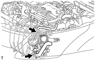
INSTALL ENGINE COVER JOINT
-
Install the engine cover joint.
- Torque:
- 8.0 N*m { 82 kgf*cm, 71 in.*lbf }
-
-
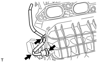
INSTALL NO. 1 GAS FILTER
-
Using a 24 mm deep socket wrench, install the gas filter to the intake manifold.
- Torque:
- 17 N*m { 173 kgf*cm, 13 ft.*lbf }
-
Connect the air hose.
-
-
INSTALL INTAKE MANIFOLD
-
w/ Stud Bolt:
-
Using an E6 "TORX" socket wrench, install the 2 stud bolts to the intake manifold.
- Torque:
- 5.0 N*m { 51 kgf*cm, 44 in.*lbf }
-
-
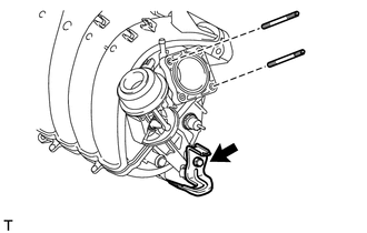
Install the wire harness clamp bracket to the intake manifold with the bolt.
- Torque:
- 15 N*m { 153 kgf*cm, 11 ft.*lbf }
-
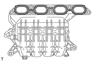
Install a new gasket to the intake manifold.
-
Install the intake manifold and intake manifold stay with the 5 bolts and 2 nuts.
- Torque:
- 28 N*m { 286 kgf*cm, 21 ft.*lbf }
-
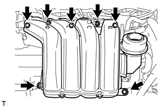
Connect the fuel vapor feed hose and ventilation hose.
-
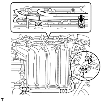
Attach the 5 clamps to the intake manifold.
-
Install the wire harness clamp bracket with the bolt.
- Torque:
- 10 N*m { 102 kgf*cm, 7 ft.*lbf }
-
-
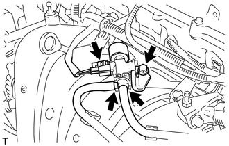
INSTALL NO. 1 VACUUM SWITCHING VALVE ASSEMBLY
-
Install the vacuum switching valve with the bolt.
- Torque:
- 10 N*m { 102 kgf*cm, 7 ft.*lbf }
-
Connect the connector and 2 vacuum hoses.
-
-
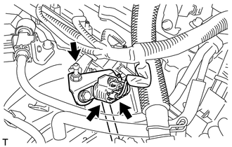
INSTALL VACUUM SENSOR ASSEMBLY
-
Connect the air hose to the vacuum sensor.
-
Install the vacuum sensor with the engine cover joint.
- Torque:
- 8.0 N*m { 82 kgf*cm, 71 in.*lbf }
-
Connect the vacuum sensor connector.
-
-
INSTALL THROTTLE BODY ASSEMBLY
-
INSTALL AIR CLEANER CAP SUB-ASSEMBLY
-
INSTALL GENERATOR ASSEMBLY
-
INSTALL V-RIBBED BELT
-
ADJUST V-RIBBED BELT
-
INSPECT V-RIBBED BELT
-
INSTALL REAR ENGINE UNDER COVER RH
-
CONNECT CABLE TO NEGATIVE BATTERY TERMINAL
Note
When disconnecting the cable, some systems need to be initialized after the cable is reconnected Click here.
-
ADD ENGINE COOLANT
-
INSPECT FOR COOLANT LEAK
-
INSTALL NO. 2 CYLINDER HEAD COVER
-
INSTALL RADIATOR SUPPORT OPENING COVER