ENGINE ASSEMBLY REMOVAL
CAUTION / NOTICE / HINT
Note
for Manual Transaxle:
When the transaxle is removed, be sure to use a new clutch release with bearing cylinder and new installation bolts. Removal of the transaxle allows the compressed clutch release with bearing cylinder to return to its original position, and dust could damage the seal of the clutch release with bearing cylinder, possibly causing clutch fluid leaks.
PROCEDURE
-
INSPECT DRIVE AWAY RELEASE FUNCTION (for Manual Transaxle)
-
DISCHARGE FUEL SYSTEM PRESSURE
-
REMOVE NO. 2 CYLINDER HEAD COVER
-
REMOVE RADIATOR SUPPORT OPENING COVER
-
PRECAUTION
Note
After turning the ignition switch off, waiting time may be required before disconnecting the cable from the battery terminal. Therefore, make sure to read the disconnecting the cable from the battery terminal notice before proceeding with work Click here.
-
DISCONNECT CABLE FROM NEGATIVE BATTERY TERMINAL
Note
When disconnecting the cable, some systems need to be initialized after the cable is reconnected Click here.
-
ALIGN FRONT WHEELS FACING STRAIGHT AHEAD
-
REMOVE FRONT LOWER BUMPER ABSORBER
-
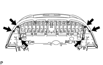
Remove the 4 screws and 2 bolts.
-
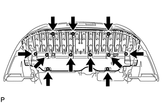
Remove the 3 screws, 8 bolts and front lower bumper absorber.
-
-
REMOVE NO. 1 ENGINE UNDER COVER
-
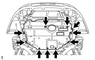
Remove the 10 clips and under cover.
-
-
REMOVE NO. 1 ENGINE UNDER COVER (for Rough Road Area Specification Vehicles)
-
Remove the 3 clips and under cover.
-
-
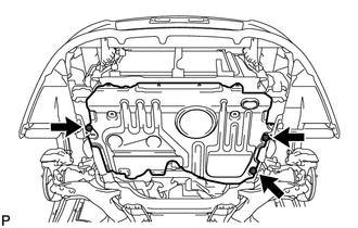
REMOVE REAR ENGINE UNDER COVER RH
-
REMOVE REAR ENGINE UNDER COVER LH
-
Remove the 5 clips and under cover.
-
-
REMOVE CENTER NO. 4 ENGINE UNDER COVER
-
Remove the 2 clips and under cover.
-
-
REMOVE NO. 2 ENGINE UNDER COVER
-
Remove the 4 clips and under cover.
-
-
DRAIN ENGINE COOLANT
-
DRAIN ENGINE OIL
-
DRAIN MANUAL TRANSAXLE OIL (for Manual Transaxle)
-
DRAIN CONTINUOUSLY VARIABLE TRANSAXLE FLUID (for CVT)
-
DISCONNECT RADIATOR RESERVOIR ASSEMBLY
-
Remove the 2 bolts and disconnect the radiator reservoir.
-
Remove the grommet from the radiator reservoir.
-
-
REMOVE V-RIBBED BELT
-
REMOVE GENERATOR ASSEMBLY
-
DISCONNECT NO. 2 RADIATOR HOSE
-
Disconnect the radiator hose from the water inlet.
-
-
DISCONNECT COMPRESSOR WITH PULLEY ASSEMBLY (w/ Air Conditioning System)
-
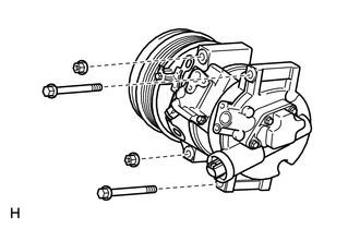
Disconnect the connector.
-
Remove the 2 bolts and 2 nuts.
-
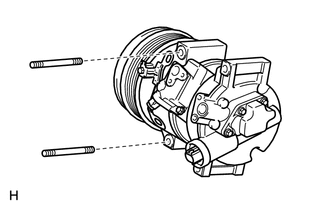
Using an E8 "TORX" socket wrench, remove the 2 stud bolts and disconnect the compressor assembly with pulley.
Tech Tips
It is not necessary to completely remove the compressor. With the hoses connected to the compressor, hang the compressor on the vehicle body with a rope.
-
-
REMOVE AIR CLEANER CAP SUB-ASSEMBLY
-
REMOVE AIR CLEANER CASE SUB-ASSEMBLY
-
REMOVE BATTERY CLAMP SUB-ASSEMBLY
-
Disconnect the cable from the positive (+) battery terminal.
-
Remove the bolt and loosen the nut.
-
Remove the battery clamp.
-
-
REMOVE BATTERY
-
REMOVE BATTERY TRAY
-
REMOVE BATTERY CARRIER
-
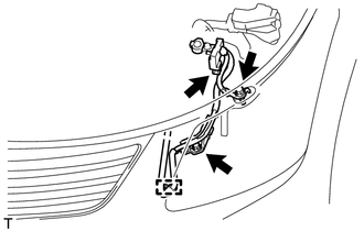
Disconnect the 2 wire harness clamps from the battery carrier.
-
Remove the 2 bolts and disconnect the radiator pipe from the battery carrier.
-
Remove the 4 bolts and battery carrier.
-
-
DISCONNECT TRANSMISSION CONTROL CABLE ASSEMBLY (for Manual Transaxle)
-

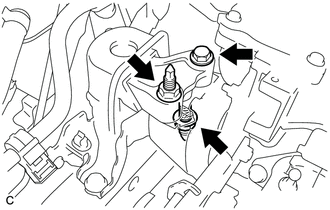
Remove the 2 clips and disconnect the 2 cables from the transaxle.
-
Remove the 2 clips and disconnect the 2 control cables from the control cable bracket.
-
Remove the nut and disconnect the control cable.
-
-
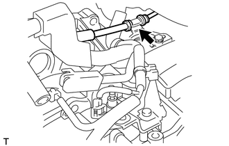
DISCONNECT TRANSMISSION CONTROL CABLE ASSEMBLY (for CVT)
-
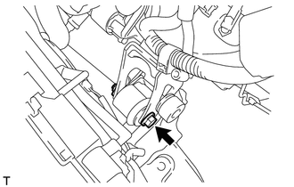
Remove the nut and disconnect the control cable from the control shaft lever.
-
Remove the clip and disconnect the transmission control cable from the control cable bracket.
-
Disconnect the control cable from the control cable bracket.
-
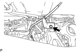
Remove the nut and disconnect the transmission control cable support together with the cable.
-
-
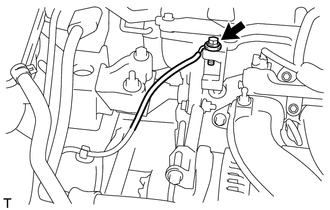
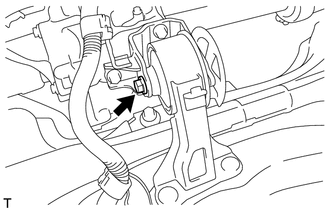
DISCONNECT CLUTCH HOSE (for Manual Transaxle)
-
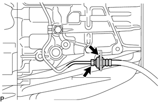
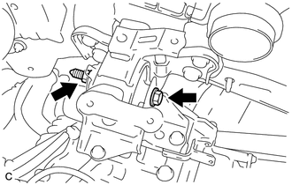
Using a 10 mm union nut wrench, disconnect the clutch hose from the flexible hose tube.
-
Remove the clip and disconnect the clutch hose.
-
-
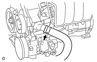
DISCONNECT NO. 1 RADIATOR HOSE
-
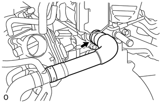
Disconnect the radiator hose from the cylinder head.
-
-
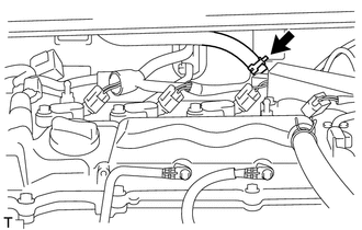
DISCONNECT FUEL TUBE SUB-ASSEMBLY
-
Release the claw and remove the No. 1 fuel pipe clamp.
-
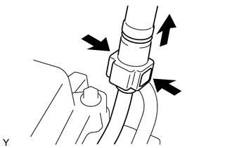
Pinch the retainer as illustrated, and then pull the fuel tube connector off of the pipe.
Note
-
Remove any dirt and foreign matter from the fuel tube connector before performing this step.
-
Do not allow any scratches or foreign matter on the parts when disconnecting the fuel tube connector, as the connector contains the O-rings that seal the pipe.
-
Perform this work by hand. Do not use any tools.
-
Do not forcibly bend, kink or twist the nylon tube.
-
Protect the disconnected parts by covering them with plastic bags after disconnecting the fuel tube.
-
If the fuel tube connector and pipe are stuck, push and pull to release them.
-
-
-
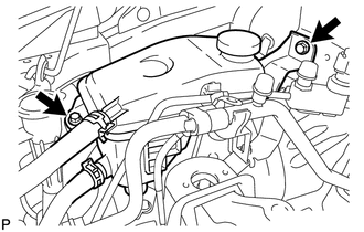
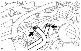
DISCONNECT HEATER WATER HOSE
-
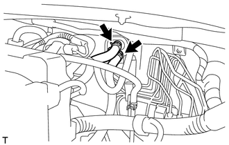
Disconnect the 2 heater water hoses.
-
-
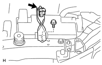
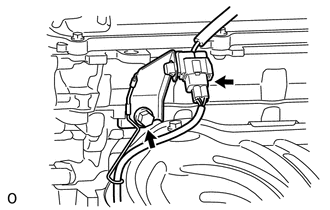
DISCONNECT WIRE HARNESS AND HOSE
-
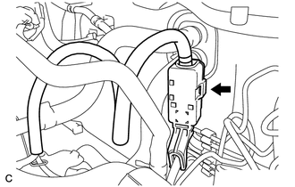
*1 Lock *2 Push Disconnect the clamp and ECM connector.
-
Raise the lever while pushing the locks on the levers, and disconnect the ECM connector.
Note
After disconnecting the connector, make sure that dirt, water or other foreign matter does not contact the connecting parts of the connector.
-
-
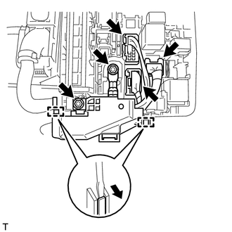
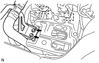
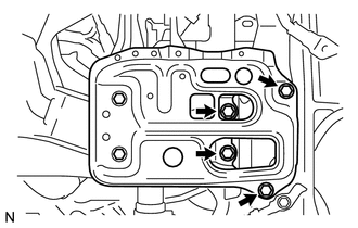
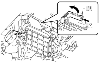
Remove the 2 nuts from the engine room No 1 relay block.
-
Disconnect the 3 connectors, detach the 2 clamps from the engine room No. 1 relay block and disconnect the wire harness.
-
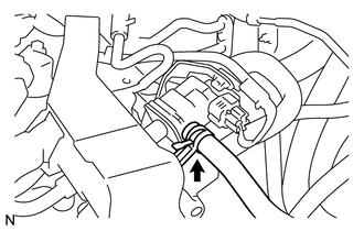
Disconnect the connector from the battery current sensor.
-
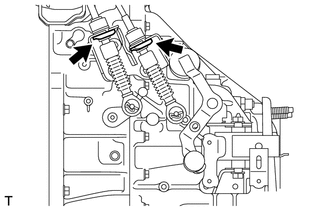
Remove the 2 bolts and disconnect the clamp and engine wire.
-
for CVT:
Disconnect the 2 oil cooler hoses from the oil cooler tube.
-
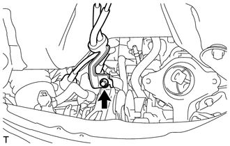
Remove the bolt and disconnect the engine wire.
-
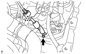
Disconnect the connector tube hose.
-
Disconnect the vacuum hose.
-
-
SECURE STEERING WHEEL ASSEMBLY
-
REMOVE COLUMN HOLE COVER SILENCER SHEET
-
DISCONNECT NO. 2 STEERING INTERMEDIATE SHAFT ASSEMBLY
-
DISCONNECT NO. 1 STEERING COLUMN HOLE COVER SUB-ASSEMBLY
-
REMOVE FRONT CENTER FLOOR BRACE
-
REMOVE FRONT EXHAUST PIPE ASSEMBLY
-
REMOVE FRONT AXLE SHAFT NUT LH
-
REMOVE FRONT AXLE SHAFT NUT RH
Tech Tips
Perform the same procedures described for the LH side.
-
DISCONNECT FRONT STABILIZER LINK ASSEMBLY LH
-
DISCONNECT FRONT STABILIZER LINK ASSEMBLY RH
Tech Tips
Perform the same procedures described for the LH side.
-
REMOVE FRONT AXLE ASSEMBLY LH
-
Remove the front axle assembly LH Click here.
-
-
REMOVE FRONT AXLE ASSEMBLY RH
Tech Tips
Perform the same procedures described for the LH side.
-
REMOVE FRONT DRIVE SHAFT ASSEMBLY LH
-
REMOVE FRONT DRIVE SHAFT ASSEMBLY RH
-
REMOVE DRIVE PLATE AND TORQUE CONVERTER SETTING BOLT (for CVT)
-
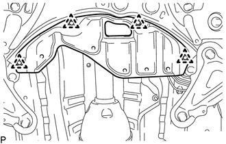
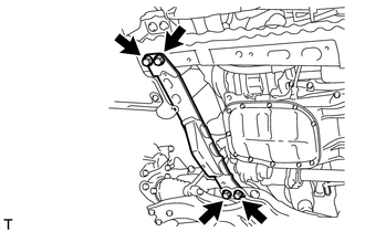
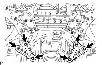
REMOVE FRONT SUSPENSION MEMBER REINFORCEMENT LH
-
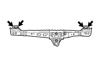
Remove the 4 bolts and front suspension member reinforcement LH.
-
-
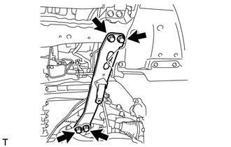
REMOVE FRONT SUSPENSION MEMBER REINFORCEMENT RH
-
Remove the 4 bolts and front suspension member reinforcement RH.
-
-
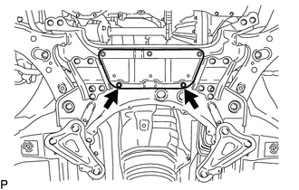
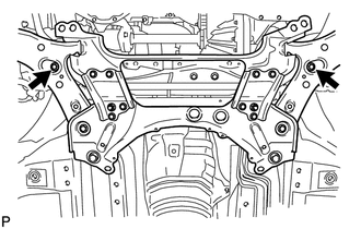
REMOVE FRONT CROSSMEMBER SUB-ASSEMBLY
-
Remove the bolt and nut.
Tech Tips
While holding the nut in place, loosen the bolt.
-
Remove the front engine mounting insulator from the front engine mounting bracket.
-
Remove the 4 bolts and front crossmember.
-
-
REMOVE ENGINE ASSEMBLY WITH TRANSAXLE
-
Set an engine lifter underneath the engine.
Note
Place the engine on wooden blocks or equivalent so that the engine is level.
-
Remove the bolt and 2 nuts, and disconnect the engine mounting insulator RH.
-
Remove the bolt and nut, and disconnect the engine mounting insulator LH.
-
Remove the 6 bolts and front suspension member brace rear RH and LH.
-
Remove the 2 bolts and front suspension crossmember.
-
Operate the engine lifter and slowly remove the engine from the vehicle.
Note
-
Make sure that the engine is clear of all wiring and hoses.
-
While lowering the engine from the vehicle, do not allow it to contact the vehicle.
-
-
-
INSTALL ENGINE HANGER
-
Disconnect the air fuel ratio sensor connector and remove the bolt and air fuel ratio sensor bracket.
-
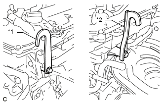
Text in Illustration *1 No. 1 Engine Hanger *2 No. 2 Engine Hanger Install the 2 engine hangers with 2 bolts as shown in the illustration.
- Torque:
- 43 N*m { 438 kgf*cm, 32 ft.*lbf }
Tech Tips
No. 1 Engine Hanger 12281-37021 No. 2 Engine Hanger 12282-37011 Bolt 91552-81050 -
Attach an engine sling device and hang the engine with a chain block.
-
-
REMOVE FRONT SUSPENSION CROSSMEMBER SUB-ASSEMBLY
-
Remove the bolt and front suspension crossmember from the engine.
-
-
REMOVE STARTER ASSEMBLY
-
REMOVE FLYWHEEL HOUSING SIDE COVER
-
REMOVE MANUAL TRANSAXLE ASSEMBLY (for Manual Transaxle)
-
Remove the manual transaxle assembly Click here.
-
-
REMOVE CONTINUOUSLY VARIABLE TRANSAXLE ASSEMBLY (for CVT)
-
Remove the continuously variable transaxle assembly Click here.
-
-
REMOVE CLUTCH COVER ASSEMBLY (for Manual Transaxle)
-
REMOVE CLUTCH DISC ASSEMBLY (for Manual Transaxle)
-
REMOVE CLUTCH RELEASE WITH BEARING CYLINDER ASSEMBLY (for Manual Transaxle)
-
Remove the clutch release with bearing cylinder assembly Click here.
-
-
REMOVE FLYWHEEL SUB-ASSEMBLY (for Manual Transaxle)
-
REMOVE DRIVE PLATE AND RING GEAR SUB-ASSEMBLY (for CVT)
-
REMOVE ENGINE WIRE
-
Remove the engine wire from the engine.
-
-
INSTALL ENGINE ON ENGINE STAND
-
Install the engine onto an engine stand with the bolts.
-
Remove the 2 bolts and 2 engine hangers.
-
-
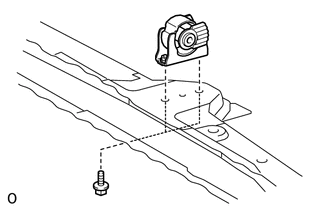
REMOVE FRONT ENGINE MOUNTING INSULATOR
Tech Tips
Perform this procedure only when replacement of the engine mounting insulator is necessary.
-
Remove the 2 bolts and front engine mounting insulator.
-
-
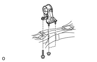
REMOVE REAR ENGINE MOUNTING INSULATOR
Tech Tips
Perform this procedure only when replacement of the engine mounting insulator is necessary.
-
Remove the 2 bolts, 2 nuts and engine mounting insulator.
-
-
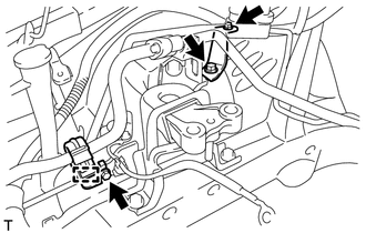
REMOVE ENGINE MOUNTING INSULATOR SUB-ASSEMBLY RH
Tech Tips
Perform this procedure only when replacement of the engine mounting insulator is necessary.
-
Disconnect the cooler pipe clamp.
-
Remove the 2 bolts, nut and 2 cooler pipe brackets.
-
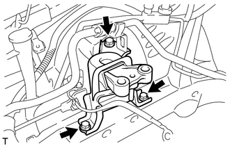
Remove the 3 bolts and engine mounting insulator.
-
-
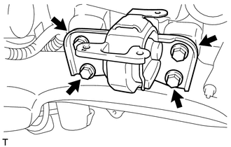
REMOVE ENGINE MOUNTING INSULATOR SUB-ASSEMBLY LH
Tech Tips
Perform this procedure only when replacement of the engine mounting insulator is necessary.
-
Remove the 4 bolts and engine mounting insulator.
-