ENGINE UNIT INSTALLATION

PROCEDURE
-
INSTALL V-RIBBED BELT TENSIONER ASSEMBLY
-
When replacing the V-ribbed belt tensioner assembly with a new one.
-
Install the V-ribbed belt tensioner assembly to the engine assembly with the 2 bolts.
- Torque:
- 21 N*m { 214 kgf*cm, 15 ft.*lbf }
Note
Make sure to install a new V-ribbed belt tensioner assembly with the pin and white cover installed to it.
-
Remove the white cover.
-
Rotate the V-ribbed belt tensioner assembly slightly clockwise and remove the pin that is used to keep the spring compressed.
Note
-
Do not forcibly rotate the V-ribbed belt tensioner assembly to the V-ribbed belt installation position with the pin installed.
-
Do not apply or add any oil or grease to the V-ribbed belt tensioner assembly.
Tech Tips
When installing the V-ribbed belt, rotate the V-ribbed belt tensioner assembly clockwise again with the pin removed, and secure the V-ribbed belt tensioner assembly using a 5 mm hexagon wrench.
-
-
-
When reusing the V-ribbed belt tensioner assembly.
-
Check that the 3 mm hexagon wrench is installed to the V-ribbed belt tensioner assembly.
-
Install the V-ribbed belt tensioner assembly to the engine assembly with the 2 bolts.
- Torque:
- 21 N*m { 214 kgf*cm, 15 ft.*lbf }
-
Rotate the V-ribbed belt tensioner assembly slightly clockwise and remove the 3 mm hexagon wrench that is used to keep the spring compressed.
Note
Do not forcibly rotate the V-ribbed belt tensioner assembly to the V-ribbed belt installation position with the 3 mm hexagon wrench installed.
Tech Tips
When installing the V-ribbed belt, rotate the V-ribbed belt tensioner assembly clockwise again with the 3 mm hexagon wrench removed, and secure the V-ribbed belt tensioner assembly using a 5 mm hexagon wrench.
-
-
-
INSTALL ENGINE OIL TEMPERATURE SENSOR
-
INSTALL NO. 1 VACUUM PUMP BRACKET
-
Install a new gasket and the vacuum pump bracket with the 2 bolts.
- Torque:
- 21 N*m { 214 kgf*cm, 15 ft.*lbf }
-
-
INSTALL VACUUM PUMP ASSEMBLY
-
INSTALL RADIO SETTING CONDENSER
-
Install the setting condenser with the bolt.
- Torque:
- 10 N*m { 102 kgf*cm, 7 ft.*lbf }
-
-
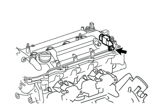
INSTALL IGNITION COIL ASSEMBLY
-
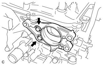
INSTALL THERMOSTAT
-
INSTALL WATER INLET
-
INSTALL WATER INLET HOSE
-
Install the water inlet hose with the 2 clamps.
-
-
INSTALL WATER BY-PASS HOSE
-
Install the water by-pass hose with the clamp.
-
-
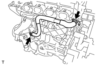
INSTALL NO. 1 WATER BY-PASS PIPE
-
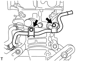
Install the water by-pass pipe with the 2 bolts.
- Torque:
- 21 N*m { 214 kgf*cm, 15 ft.*lbf }
-
-
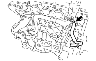
CONNECT NO. 3 WATER BY-PASS HOSE
-
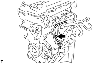
INSTALL VENTILATION HOSE
-
Install the ventilation hose to the ventilation valve.
-
-
INSTALL IDLER PULLEY BRACKET (w/o Air Conditioning System)
-
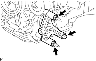
Install the idler pulley bracket with the 2 nuts and bolt.
- Torque:
- 25 N*m { 255 kgf*cm, 18 ft.*lbf }
-
-
INSTALL IDLER PULLEY SUB-ASSEMBLY NO.1 (w/o Air Conditioning System)
-
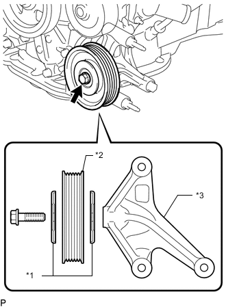
Text in Illustration *1 Idler Pulley Cover Plate *2 No. 1 Idler Pulley Sub-assembly *3 Idler Pulley Bracket Install the 2 idler pulley cover plates and bolt to the No. 1 idler pulley sub-assembly as shown in the illustration.
-
Tighten the bolt by hand until the flange of the bolt contacts the idler pulley cover plate and the No. 1 idler pulley sub-assembly is fixed in place.
Note
Do not use any tools.
-
Tighten the bolt.
- Torque:
- 60 N*m { 612 kgf*cm, 44 ft.*lbf }
-
-
INSTALL EXHAUST MANIFOLD
-
INSTALL MANIFOLD STAY
-
INSTALL DRIVE SHAFT HEAT INSULATOR SUB-ASSEMBLY
-
INSTALL NO. 1 EXHAUST MANIFOLD HEAT INSULATOR
-
INSTALL ENGINE OIL LEVEL DIPSTICK GUIDE
-
Apply a light coat of engine oil to a new O-ring.
-
Install the O-ring to the dipstick guide.
-
Install the dipstick guide with the bolt.
- Torque:
- 21 N*m { 214 kgf*cm, 15 ft.*lbf }
-
Install the engine oil level dipstick.
-
-
INSTALL FUEL INJECTOR ASSEMBLY
-
INSTALL NO. 1 DELIVERY PIPE SPACER
-
INSTALL FUEL DELIVERY PIPE SUB-ASSEMBLY
-
INSTALL FUEL TUBE SUB-ASSEMBLY
-
INSTALL WIRE HARNESS CLAMP BRACKET
-
INSTALL AIR TUBE
-
INSTALL INTAKE MANIFOLD
-
INSTALL THROTTLE BODY ASSEMBLY