SFI SYSTEM, Diagnostic DTC:P0031, P0032, P101D
| DTC Code | DTC Name |
|---|---|
| P0031 | Oxygen (A/F) Sensor Heater Control Circuit Low (Bank 1 Sensor 1) |
| P0032 | Oxygen (A/F) Sensor Heater Control Circuit High (Bank 1 Sensor 1) |
| P101D | A/F Sensor Heater Circuit Performance Bank 1 Sensor 1 Stuck ON |
DESCRIPTION
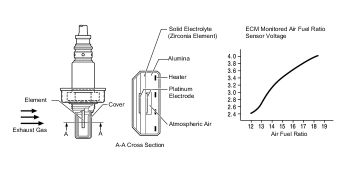
A three way catalytic converter is used in order to convert the carbon monoxide, hydrocarbons and oxides of nitrogen in the exhaust into less harmful substances. To allow the three way catalytic converter to function effectively, it is necessary to keep the air fuel ratio of the engine near the stoichiometric air fuel ratio. For the purpose of helping the ECM to deliver accurate air fuel ratio control, an air fuel ratio sensor is used. The air fuel ratio sensor generates a voltage that corresponds to the actual air fuel ratio. This sensor voltage is used to provide the ECM with feedback so that it can control the air fuel ratio. The sensor uses a zirconia element that is made of platinum coated zirconia with an integrated heater. The inner surface of the zirconia element is exposed to the ambient air while the outer surface is exposed to the exhaust gas. If the oxygen concentration greatly differs between the ambient air and the exhaust gas, a slight voltage will be generated. Since the sensor has the property of generating more voltage when heated, if the temperature of the exhaust gas is low, the sensor will not generate sufficient voltage without additional heating. Therefore, the air fuel ratio sensor has a heater to heat the zirconia element, allowing the ECM to regulate additional heating using duty cycle control to adjust the average current to the heater.
Tech Tips
-
Although the DTC titles refer to the oxygen sensor, these DTCs relate to the air fuel ratio sensor.
-
Sensor 1 refers to the sensor mounted in front of the three way catalytic converter and located near the engine assembly.
-
When either of these DTCs are stored, the ECM enters fail-safe mode. The ECM turns off the air fuel ratio sensor heater in fail-safe mode. Fail-safe mode continues until the ignition switch is turned off.
-
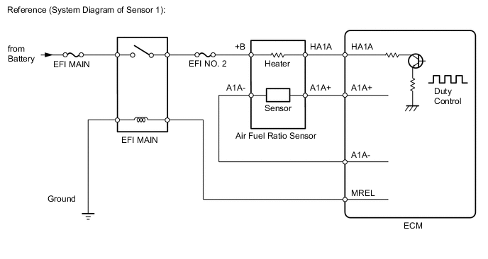
The ECM provides a pulse width modulated signal to the control circuit to adjust the current through the heater. The air fuel ratio sensor heater circuit uses a relay on the +B side of the circuit.
| DTC No. | DTC Detection Condition | Trouble Area |
|---|---|---|
| P0031 | The Air Fuel Ratio (A/F) sensor heater current is below 0.8 A (1 trip detection logic). |
|
| P0032 | The Air Fuel Ratio (A/F) sensor heater current is higher than 10 A (1 trip detection logic). |
|
| P101D | The heater current is higher than the specified value while the heater is not operating (1 trip detection logic). | ECM |
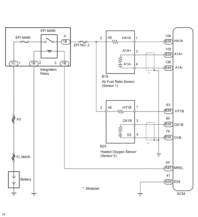
WIRING DIAGRAM
CAUTION / NOTICE / HINT
Note
Inspect the fuses for circuits related to this system before performing the following inspection procedure.
Tech Tips
Read freeze frame data using the intelligent tester. Freeze frame data records the engine condition when malfunctions are detected. When troubleshooting, freeze frame data can help determine if the vehicle was moving or stationary, if the engine was warmed up or not, if the air fuel ratio was lean or rich, and other data from the time the malfunction occurred.
PROCEDURE
-
INSPECT AIR FUEL RATIO SENSOR (HEATER RESISTANCE)
-
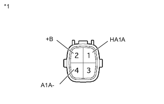
Text in Illustration *1 Component without harness connected
(Air Fuel Ratio Sensor [Sensor 1])
Disconnect the air fuel ratio sensor connector.
-
Measure the resistance according to the value(s) in the table below.
Standard Resistance Tester Connection Condition Specified Condition 1 (HA1A) - 2 (+B) 20°C (68°F) 1.8 to 3.4 Ω 1 (HA1A) - 4 (A1A-) Always 10 kΩ or higher -
Reconnect the air fuel ratio sensor connector.
NG 
REPLACE AIR FUEL RATIO SENSOR Click here
OK 
-
-
CHECK TERMINAL VOLTAGE (POWER SOURCE)
-
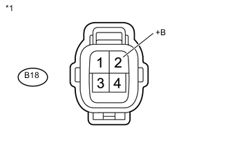
Text in Illustration *1 Front view of wire harness connector
(to Air Fuel Ratio Sensor [Sensor 1])
Disconnect the air fuel ratio sensor connector.
-
Measure the voltage according to the value(s) in the table below.
Standard Voltage Tester Connection Switch Condition Specified Condition B18-2 (+B) - Body ground Ignition switch ON 11 to 14 V -
Reconnect the air fuel ratio sensor connector.
NG 
CHECK HARNESS AND CONNECTOR (AIR FUEL RATIO SENSOR - INTEGRATION RELAY (EFI MAIN RELAY)) Click here
OK
-
-
CHECK HARNESS AND CONNECTOR (AIR FUEL RATIO SENSOR - ECM)
-
Disconnect the air fuel ratio sensor connector.
-
Disconnect the ECM connector.
-
Measure the resistance according to the value(s) in the table below.
Standard Resistance (Check for Open) Tester Connection Condition Specified Condition B18-1 (HA1A) - B39-104 (HA1A) Always Below 1 Ω Standard Resistance (Check for Short) Tester Connection Condition Specified Condition B18-1 (HA1A) or B39-104 (HA1A) - Body ground Always 10 kΩ or higher -
Reconnect the air fuel ratio sensor connector.
-
Reconnect the ECM connector.
OK
REPLACE ECM Click here
NG
REPAIR OR REPLACE HARNESS OR CONNECTOR (AIR FUEL RATIO SENSOR - ECM)
-
-
CHECK HARNESS AND CONNECTOR (AIR FUEL RATIO SENSOR - INTEGRATION RELAY (EFI MAIN RELAY))
-
Disconnect the air fuel ratio sensor connector.
-
Remove the integration relay (EFI MAIN relay) from the engine room No. 1 relay block.
-
Measure the resistance according to the value(s) in the table below.
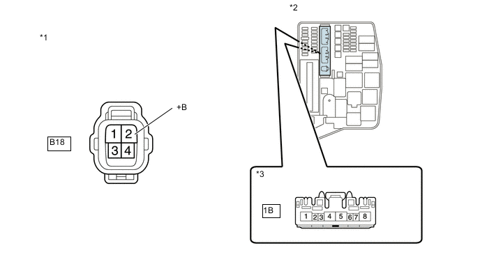
Standard Resistance (Check for Open) Tester Connection Condition Specified Condition B18-2 (+B) - 1B-4 Always Below 1 Ω Standard Resistance (Check for Short) Tester Connection Condition Specified Condition B18-2 (+B) or 1B-4 - Body ground Always 10 kΩ or higher Text in Illustration *1 Front view of wire harness connector
(to Air Fuel Ratio Sensor [Sensor 1])
*2 Engine Room No. 1 Relay Block *3 Front view of wire harness connector
(to Integration Relay)
-
Reinstall the integration relay.
-
Reconnect the air fuel ratio sensor connector.
OK
CHECK ECM POWER SOURCE CIRCUIT Click here
NG
REPAIR OR REPLACE HARNESS OR CONNECTOR (AIR FUEL RATIO SENSOR - INTEGRATION RELAY (EFI MAIN RELAY))
-