SFI SYSTEM Fuel Pump Control Circuit
DESCRIPTION
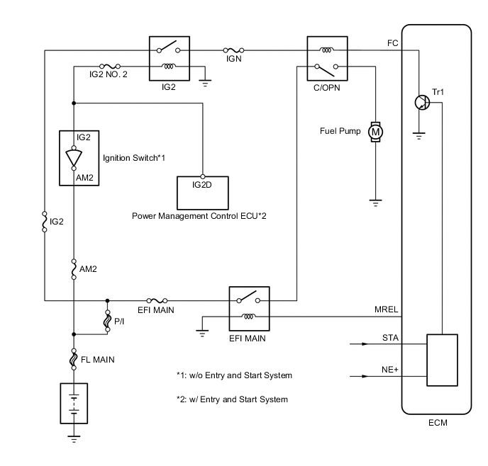
When the engine is cranked, the starter relay drive signal output from the ignition switch*1 or power management control ECU*2 is input into the STA terminal of the ECM, and the NE signal generated by the crankshaft position sensor is also input into the NE+ terminal. The ECM interprets that the engine is cranked, and turns transistor Tr1 in the ECM internal circuit on. The current flows to the C/OPN (Circuit Opening) relay by turning Tr1 on.
Then, the fuel pump operates.
While the NE signal is input into the ECM, when the engine is running, the ECM turns Tr1 on continuously.
-
*1: w/o Entry and Start System
-
*2: w/ Entry and Start System
WIRING DIAGRAM
CAUTION / NOTICE / HINT
Note
Inspect the fuses for circuits related to this system before performing the following inspection procedure.
PROCEDURE
-
PERFORM ACTIVE TEST USING INTELLIGENT TESTER (OPERATE C/OPN RELAY)
-
Connect the intelligent tester to the DLC3.
-
Turn the ignition switch to ON.
-
Turn the tester on.
-
Enter the following menus: Powertrain / Engine and ECT / Active Test / Control the Fuel Pump / Speed.
-
Check whether the fuel pump operation sound occurs when performing the Active Test on the tester.
OK Fuel pump operating sound occurs.
OK 
PROCEED TO NEXT CIRCUIT INSPECTION SHOWN IN PROBLEM SYMPTOMS TABLE Click here
NG 
-
-
INSPECT INSTRUMENT PANEL JUNCTION BLOCK (C/OPN RELAY)
-
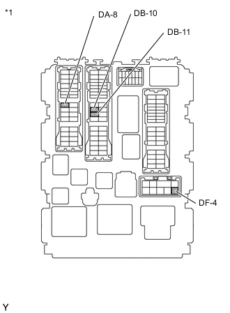
Text in Illustration *1 Component without harness connected
(Instrument Panel Junction Block)
Disconnect the instrument panel junction block connector.
-
Measure the resistance according to the value(s) in the table below.
Standard Resistance Tester Connection Condition Specified Condition DA-8 - DB-11 Battery voltage is not applied to terminals DB-10 and DF-4 10 kΩ or higher Battery voltage is applied to terminals DB-10 and DF-4 Below 1 Ω -
Reconnect the instrument panel junction block connector.
NG
REPLACE INSTRUMENT PANEL JUNCTION BLOCK (C/OPN RELAY)
OK
-
-
CHECK HARNESS AND CONNECTOR (C/OPN RELAY - ECM)
-
Disconnect the ECM connector.
-
Disconnect the instrument panel junction block connector.
-
Measure the resistance according to the value(s) in the table below.
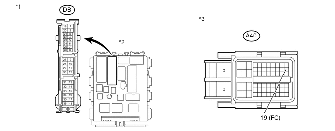
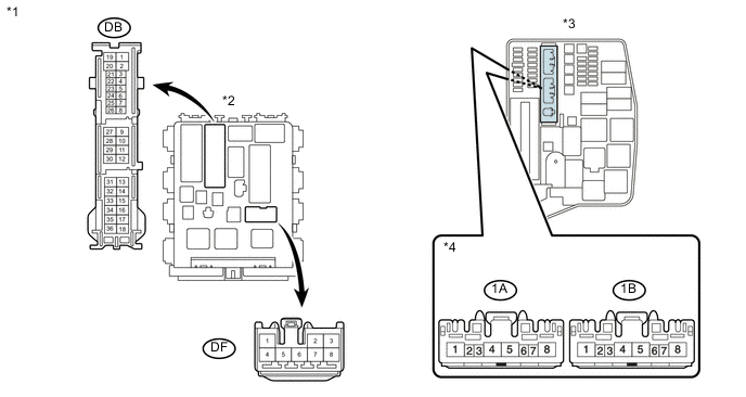
Standard Resistance (Check for open) Tester Connection Condition Specified Condition DB-10 - A40-19 (FC) Always Below 1 Ω Standard Resistance (Check for short) Tester Connection Condition Specified Condition DB-10 or A40-19 (FC) - Body ground Always 10 kΩ or higher Text in Illustration *1 Front view of wire harness connector
(to Instrument Panel Junction Block)
*2 Instrument Panel Junction Block *3 Front view of wire harness connector
(to ECM)
-
Reconnect the ECM connector.
-
Reconnect the instrument panel junction block connector.
NG
REPAIR OR REPLACE HARNESS OR CONNECTOR (C/OPN RELAY - ECM)
OK
-
-
CHECK HARNESS AND CONNECTOR (C/OPN RELAY - INTEGRATION RELAY (EFI MAIN RELAY, IG2 RELAY))
-
Remove the integration relay from engine room No. 1 relay block.
-
Disconnect the integration relay connector.
-
Disconnect the instrument panel junction block connector.
-
Measure the resistance according to the value(s) in the table below.
Standard Resistance (Check for open) Tester Connection Condition Specified Condition DB-11 - 1B-4 Always Below 1 Ω DF-4 - 1A-4 Always Below 1 Ω Standard Resistance (Check for short) Tester Connection Condition Specified Condition DB-11 or 1B-4 - Body ground Always 10 kΩ or higher DF-4 or 1A-4 - Body ground Always 10 kΩ or higher Text in Illustration *1 Front view of wire harness connector
(to Instrument Panel Junction Block)
*2 Instrument Panel Junction Block *3 Engine Room No. 1 Relay Block *4 Front view of wire harness connector
(to Integration Relay)
-
Reconnect the instrument panel junction block connector.
-
Reconnect the integration relay connector.
-
Reinstall the integration relay.
NG
REPAIR OR REPLACE HARNESS OR CONNECTOR (C/OPN RELAY - INTEGRATION RELAY (EFI MAIN RELAY, IG2 RELAY))
OK
-
-
CHECK HARNESS AND CONNECTOR (C/OPN RELAY - FUEL PUMP)
-
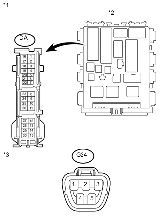
Text in Illustration *1 Front view of wire harness connector
(to Instrument Panel Junction Block)
*2 Instrument Panel Junction Block *3 Front view of wire harness connector
(to Fuel Pump)
Disconnect the fuel pump connector.
-
Disconnect the instrument panel junction block connector.
-
Measure the resistance according to the value(s) in the table below.
Standard Resistance (Check for open) Tester Connection Condition Specified Condition DA-8 - G24-4 Always Below 1 Ω Standard Resistance (Check for short) Tester Connection Condition Specified Condition DA-8 or G24-4 - Body ground Always 10 kΩ or higher -
Reconnect the instrument panel junction block connector.
-
Reconnect the fuel pump connector.
NG
REPAIR OR REPLACE HARNESS OR CONNECTOR (C/OPN RELAY - FUEL PUMP)
OK
-
-
CHECK HARNESS AND CONNECTOR (FUEL PUMP - BODY GROUND)
-
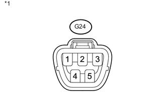
Text in Illustration *1 Front view of wire harness connector
(to Fuel Pump)
Disconnect the fuel pump connector.
-
Measure the resistance according to the value(s) in the table below.
Standard Resistance Tester Connection Condition Specified Condition G24-5 - Body ground Always Below 1 Ω -
Reconnect the fuel pump connector.
NG
REPAIR OR REPLACE HARNESS OR CONNECTOR (FUEL PUMP - BODY GROUND)
OK
-
-
INSPECT FUEL PUMP
-
Inspect the fuel pump Click here.
NG
REPLACE FUEL PUMP Click here
OK
-
-
CHECK ECM POWER SOURCE CIRCUIT
-
Check the ECM power source circuit Click here.
OK
REPLACE ECM Click here
NG
REPAIR OR REPLACE ECM POWER SOURCE CIRCUIT
-