SFI SYSTEM ECM Power Source Circuit
DESCRIPTION
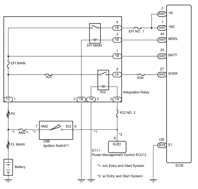
When the ignition switch is turned to ON, the battery voltage is applied to IGSW of the ECM. The output signal from the MREL terminal of the ECM causes a current to flow to the coil, closing the contacts of the integration relay (EFI MAIN relay) and supplying power to either terminal +B or +B2 of the ECM.
WIRING DIAGRAM
CAUTION / NOTICE / HINT
Note
Inspect the fuses for circuits related to this system before performing the following inspection procedure.
PROCEDURE
-
CHECK HARNESS AND CONNECTOR (ECM - BODY GROUND)
-
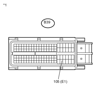
Text in Illustration *1 Front view of wire harness connector
(to ECM)
Disconnect the ECM connector.
-
Measure the resistance according to the value(s) in the table below.
Standard Resistance Tester Connection Condition Specified Condition B39-105 (E1) - Body ground Always Below 1 Ω -
Reconnect the ECM connector.
NG 
REPAIR OR REPLACE HARNESS OR CONNECTOR (ECM - BODY GROUND)
OK 
-
-
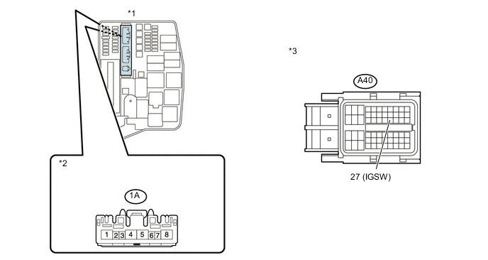
INSPECT ECM (IGSW VOLTAGE)
-
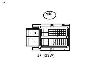
Text in Illustration *1 Front view of wire harness connector
(to ECM)
Disconnect the ECM connector.
-
Turn the ignition switch to ON.
-
Measure the voltage according to the value(s) in the table below.
Standard Voltage Tester Connection Switch Condition Specified Condition A40-27 (IGSW) - Body ground Ignition switch ON 11 to 14 V -
Reconnect the ECM connector.
NG 
INSPECT INTEGRATION RELAY (IG2 RELAY) Click here
OK
-
-
INSPECT INTEGRATION RELAY (EFI MAIN RELAY)
-
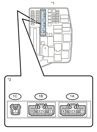
Text in Illustration *1 Engine Room No. 1 Relay Block *2 Component without harness connected
(Integration Relay)
Remove the integration relay from the engine room No. 1 relay block.
-
Disconnect the integration relay connector.
-
Measure the resistance according to the value(s) in the table below.
Standard Resistance Tester Connection Condition Specified Condition 1C-1 - 1B-4 Battery voltage is not applied to terminals 1B-2 and 1B-3 10 kΩ or higher Battery voltage is applied to terminals 1B-2 and 1B-3 Below 1 Ω -
Reconnect the integration relay connector.
-
Reinstall the integration relay.
NG
REPLACE INTEGRATION RELAY Click here
OK
-
-
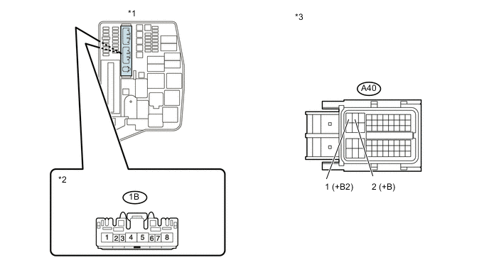
CHECK HARNESS AND CONNECTOR (INTEGRATION RELAY (EFI MAIN RELAY) - ECM)
-
Remove the integration relay from the engine room No. 1 relay block.
-
Disconnect the integration relay connector.
-
Disconnect the ECM connector.
-
Measure the resistance according to the value(s) in the table below.
Standard Resistance (Check for open) Tester Connection Condition Specified Condition 1B-4 - A40-2 (+B) Always Below 1 Ω 1B-4 - A40-1 (+B2) Always Below 1 Ω Standard Resistance (Check for short) Tester Connection Condition Specified Condition 1B-4 or A40-2 (+B) - Body ground Always 10 kΩ or higher 1B-4 or A40-1 (+B2) - Body ground Always 10 kΩ or higher Text in Illustration *1 Engine Room No. 1 Relay Block *2 Front view of wire harness connector
(to Integration Relay)
*3 Front view of wire harness connector
(to ECM)
-
Reconnect the ECM connector.
-
Reconnect the integration relay connector.
-
Reinstall the integration relay.
NG
REPAIR OR REPLACE HARNESS OR CONNECTOR (INTEGRATION RELAY (EFI MAIN RELAY) - ECM)
OK
-
-
CHECK HARNESS AND CONNECTOR (EFI MAIN RELAY - BATTERY)
-
Disconnect the negative battery terminal.
-
Disconnect the positive battery terminal.
-
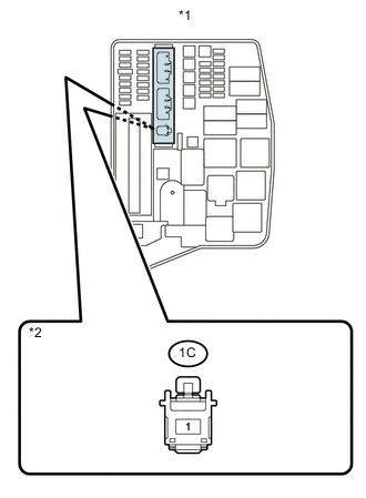
Text in Illustration *1 Engine Room No. 1 Relay Block *2 Front view of wire harness connector
(to Integration Relay)
Remove the integration relay from the engine room No. 1 relay block.
-
Disconnect the integration relay connector.
-
Measure the resistance according to the value(s) in the table below.
Standard Resistance (Check for open) Tester Connection Condition Specified Condition 1C-1 - Battery positive terminal Always Below 1 Ω Standard Resistance (Check for short) Tester Connection Condition Specified Condition 1C-1 or Battery positive terminal - Body ground Always 10 kΩ or higher -
Reconnect the integration relay connector.
-
Reinstall the integration relay.
-
Reconnect the positive battery terminal.
-
Reconnect the negative battery terminal.
NG
REPAIR OR REPLACE HARNESS OR CONNECTOR (EFI MAIN RELAY - BATTERY)
OK
-
-
CHECK HARNESS AND CONNECTOR (INTEGRATION RELAY (EFI MAIN RELAY) - BODY GROUND)
-
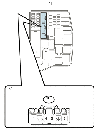
Text in Illustration *1 Engine Room No. 1 Relay Block *2 Front view of wire harness connector
(to Integration Relay)
Remove the integration relay from the engine room No. 1 relay block.
-
Disconnect the integration relay connector.
-
Measure the resistance according to the value(s) in the table below.
Standard Resistance Tester Connection Condition Specified Condition 1B-2 - Body ground Always Below 1 Ω -
Reconnect the integration relay connector.
-
Reinstall the integration relay.
NG
REPAIR OR REPLACE HARNESS OR CONNECTOR (INTEGRATION RELAY (EFI MAIN RELAY) - BODY GROUND)
OK
-
-
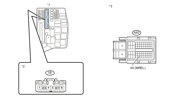
CHECK HARNESS AND CONNECTOR (INTEGRATION RELAY (EFI MAIN RELAY) - ECM)
-
Disconnect the ECM connector.
-
Remove the integration relay from the engine room No. 1 relay block.
-
Disconnect the integration relay connector.
-
Measure the resistance according to the value(s) in the table below.
Standard Resistance (Check for open) Tester Connection Condition Specified Condition 1B-3 - A40-44 (MREL) Always Below 1 Ω Standard Resistance (Check for short) Tester Connection Condition Specified Condition 1B-3 or A40-44 (MREL) - Body ground Always 10 kΩ or higher Text in Illustration *1 Engine Room No. 1 Relay Block *2 Front view of wire harness connector
(to Integration Relay)
*3 Front view of wire harness connector
(to ECM)
-
Reconnect the ECM connector.
-
Reconnect the integration relay connector.
-
Reinstall the integration relay.
OK
REPLACE ECM Click here
NG
REPAIR OR REPLACE HARNESS OR CONNECTOR (INTEGRATION RELAY (EFI MAIN RELAY) - ECM)
-
-
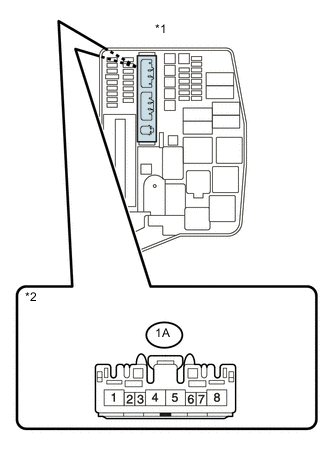
INSPECT INTEGRATION RELAY (IG2 RELAY)
-
Text in Illustration *1 Engine Room No. 1 Relay Block *2 Component without harness connected
(Integration Relay)
Remove the integration relay from the engine room No. 1 relay block.
-
Disconnect the integration relay connector.
-
Measure the resistance according to the value(s) in the table below.
Standard Resistance Tester Connection Condition Specified Condition 1C-1 - 1A-4 Battery voltage is not applied to terminals 1A-2 and 1A-3 10 kΩ or higher Battery voltage is not applied to terminals 1A-2 and 1A-3 Below 1 Ω -
Reconnect the integration relay connector.
-
Reinstall the integration relay.
NG
REPLACE INTEGRATION RELAY Click here
OK
-
-
CHECK HARNESS AND CONNECTOR (INTEGRATION RELAY (IG2 RELAY) - ECM)
-
Disconnect the ECM connector.
-
Remove the integration relay from the engine room No. 1 relay block.
-
Disconnect the integration relay connector.
-
Measure the resistance according to the value(s) in the table below.
Standard Resistance (Check for open) Tester Connection Condition Specified Condition 1A-4 - A40-27 (IGSW) Always Below 1 Ω Standard Resistance (Check for short) Tester Connection Condition Specified Condition 1A-4 or A40-27 (IGSW) - Body ground Always 10 kΩ or higher Text in Illustration *1 Engine Room No. 1 Relay Block *2 Front view of wire harness connector
(to Integration Relay)
*3 Front view of wire harness connector
(to ECM)
-
Reconnect the ECM connector.
-
Reconnect the integration relay connector.
-
Reinstall the integration relay.
NG
REPAIR OR REPLACE HARNESS OR CONNECTOR (INTEGRATION RELAY (IG2 RELAY) - ECM)
OK
-
-
CHECK HARNESS AND CONNECTOR (INTEGRATION RELAY (IG2 RELAY) - BATTERY)
-
Disconnect the negative battery terminal.
-
Disconnect the positive battery terminal.
-
Text in Illustration *1 Engine Room No. 1 Relay Block *2 Front view of wire harness connector
(to Integration Relay)
Remove the integration relay from the engine room No. 1 relay block.
-
Disconnect the integration relay connector.
-
Measure the resistance according to the value(s) in the table below.
Standard Resistance (Check for open) Tester Connection Condition Specified Condition 1C-1 - Battery positive terminal Always Below 1 Ω Standard Resistance (Check for short) Tester Connection Condition Specified Condition 1C-1 or Battery positive terminal - Body ground Always 10 kΩ or higher -
Reconnect the integration relay connector.
-
Reinstall the integration relay.
-
Reconnect the positive battery terminal.
-
Reconnect the negative battery terminal.
NG
REPAIR OR REPLACE HARNESS OR CONNECTOR (INTEGRATION RELAY (IG2 RELAY) - BATTERY)
OK
-
-
CHECK HARNESS AND CONNECTOR (INTEGRATION RELAY (IG2 RELAY) - BODY GROUND)
-
Text in Illustration *1 Engine Room No. 1 Relay Block *2 Front view of wire harness connector
(to Integration Relay)
Remove the integration relay from the engine room No. 1 relay block.
-
Disconnect the integration relay connector.
-
Measure the resistance according to the value(s) in the table below.
Standard Resistance Tester Connection Condition Specified Condition 1A-2 - Body ground Always Below 1 Ω -
Reconnect the integration relay connector.
-
Reinstall the integration relay.
NG
REPAIR OR REPLACE HARNESS OR CONNECTOR (INTEGRATION RELAY (IG2 RELAY) - BODY GROUND)
OK
-
-
CHECK IF VEHICLE IS EQUIPPED WITH ENTRY AND START SYSTEM
-
Confirm the entry and start system.
Result Result Proceed to w/o Entry and Start System A w/ Entry and Start System B
B
CHECK HARNESS AND CONNECTOR (INTEGRATION RELAY - POWER MANAGEMENT CONTROL ECU) Click here
A
-
-
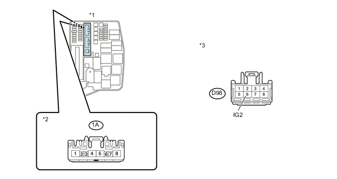
CHECK HARNESS AND CONNECTOR (INTEGRATION RELAY (IG2 RELAY) - IGNITION SWITCH)
-
Disconnect the ignition switch connector.
-
Remove the integration relay from the engine room No. 1 relay block.
-
Disconnect the integration relay connector.
-
Measure the resistance according to the value(s) in the table below.
Standard Resistance (Check for open) Tester Connection Condition Specified Condition 1A-3 - D98-6 (IG2) Always Below 1 Ω Standard Resistance (Check for short) Tester Connection Condition Specified Condition 1A-3 or D98-6 (IG2) - Body ground Always 10 kΩ or higher Text in Illustration *1 Engine Room No. 1 Relay Block *2 Front view of wire harness connector
(to Integration Relay)
*3 Front view of wire harness connector
(to Ignition Switch)
-
Reconnect the ignition switch connector.
-
Reconnect the integration relay connector.
-
Reinstall the integration relay.
NG
REPAIR OR REPLACE HARNESS OR CONNECTOR (INTEGRATION RELAY (IG2 RELAY) - IGNITION SWITCH)
OK
-
-
INSPECT IGNITION SWITCH ASSEMBLY
-
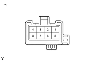
Text in Illustration *1 Component without harness connected
(Ignition Switch)
Disconnect the ignition switch assembly connector.
-
Measure the resistance according to the value(s) in the table below.
Standard Resistance Tester Connection Switch Condition Specified Condition All Terminals Off 10 kΩ or higher 2 - 4 ACC Below 1 Ω 1 - 2 - 4, 5 - 6 ON 1 - 3 - 4, 5 - 6 - 7 START -
Reconnect the ignition switch assembly connector.
OK
REPAIR OR REPLACE HARNESS OR CONNECTOR (IGNITION SWITCH - BATTERY)
NG
REPLACE IGNITION SWITCH ASSEMBLY Click here
-
-
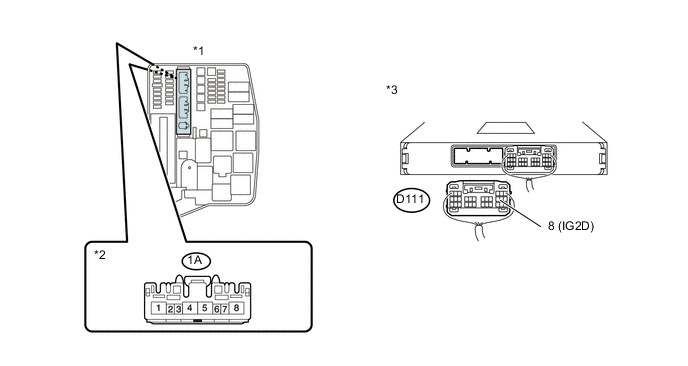
CHECK HARNESS AND CONNECTOR (INTEGRATION RELAY - POWER MANAGEMENT CONTROL ECU)
-
Disconnect the power management control ECU connector.
-
Remove the integration relay from the engine room No. 1 relay block.
-
Disconnect the integration relay connector.
-
Measure the resistance according to the value(s) in the table below.
Standard Resistance (Check for open) Tester Connection Condition Specified Condition 1A-3 - D111-8 (IG2D) Always Below 1 Ω Standard Resistance (Check for short) Tester Connection Condition Specified Condition 1A-3 or D111-8 (IG2D) - Body ground Always 10 kΩ or higher Text in Illustration *1 Engine Room No. 1 Relay Block *2 Front view of wire harness connector
(to Integration Relay)
*3 Rear view of wire harness connector
(to Power Management Control ECU)
-
Reconnect the power management control ECU connector.
-
Reconnect the integration relay connector.
-
Reinstall the integration relay.
OK
CHECK ENTRY AND START SYSTEM Click here
NG
REPAIR OR REPLACE HARNESS OR CONNECTOR (INTEGRATION RELAY - POWER MANAGEMENT CONTROL ECU)
-