CONTINUOUSLY VARIABLE TRANSAXLE SYSTEM Shift Paddle Switch Circuit
DESCRIPTION
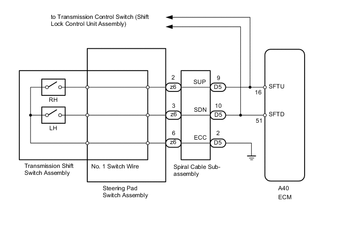
When the shift lever is in M, the shift range can be changed using the shift paddle switches. It is also possible to select the shift range when the vehicle is being driven with the shift lever in D by operating the shift paddle switches.
WIRING DIAGRAM
PROCEDURE
-
CHECK HARNESS AND CONNECTOR (SPIRAL CABLE - BODY GROUND)
-
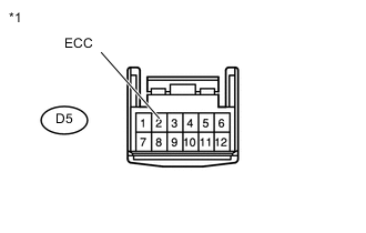
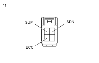
Text in Illustration *1 Front view of wire harness connector
(to Spiral Cable Sub-assembly)
Disconnect the spiral cable connector.
-
Measure the resistance according to the value(s) in the table below.
Standard Resistance Tester Connection Condition Specified Condition D5-2 (ECC) - Body ground Always Below 1 Ω
NG 
REPAIR OR REPLACE HARNESS OR CONNECTOR
OK 
-
-
INSPECT SPIRAL CABLE SUB-ASSEMBLY
-
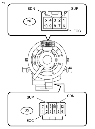
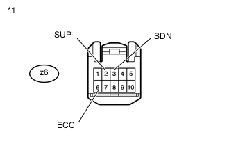
Text in Illustration *1 Component without harness connected
(Spiral Cable Sub-assembly)
Remove the spiral cable sub-assembly Click here.
-
Measure the resistance according to the value(s) in the table below.
Standard Resistance Tester Connection Condition Specified Condition z6-2 (SUP) - D5-9 (SUP) Always Below 1 Ω z6-3 (SDN) - D5-10 (SDN) Always Below 1 Ω z6-6 (ECC) - D5-2 (ECC) Always Below 1 Ω
NG
REPLACE SPIRAL CABLE SUB-ASSEMBLY Click here
OK
-
-
INSPECT TRANSMISSION SHIFT SWITCH ASSEMBLY (LH (-) AND RH (+))
-
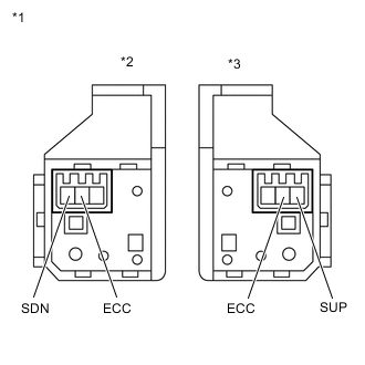
Text in Illustration *1 Component without harness connected
(Transmission Shift Switch Assembly)
*2 for LH *3 for RH Remove the transmission shift switch assembly Click here.
-
Measure the resistance according to the value(s) in the table below.
Standard Resistance for LH Tester Connection Switch Condition Specified Condition SDN - ECC "-" shift paddle operated and held (down-shift) Below 2.5 Ω SDN - ECC "-" shift paddle not operated (down-shift) 1 MΩ or higher for RH Tester Connection Switch Condition Specified Condition SUP - ECC "+" shift paddle operated and held (up-shift) Below 2.5 Ω SUP - ECC "+" shift paddle not operated (up-shift) 1 MΩ or higher
NG
REPLACE TRANSMISSION SHIFT SWITCH ASSEMBLY Click here
OK
-
-
INSPECT NO. 1 SWITCH WIRE
-
Text in Illustration *1 Component without harness connected
(No. 1 Switch Wire)
Disconnect the No. 1 switch wire connector.
-
Measure the resistance according to the value(s) in the table below.
Standard Resistance Tester Connection Switch Condition Specified Condition SDN - ECC "-" shift paddle operated and held (down-shift) Below 2.5 Ω SUP - ECC "+" shift paddle operated and held (up-shift) Below 2.5 Ω SDN - ECC "-" shift paddle not operated (down-shift) 1 MΩ or higher SUP - ECC "+" shift paddle not operated (up-shift) 1 MΩ or higher
NG
REPLACE NO. 1 SWITCH WIRE Click here
OK
-
-
INSPECT STEERING PAD SWITCH ASSEMBLY
-
Text in Illustration *1 Front view of wire harness connector
(to Spiral Cable Sub-assembly)
Disconnect the steering pad switch assembly connector.
-
Measure the resistance according to the value(s) in the table below.
Standard Resistance Tester Connection Switch Condition Specified Condition z6-2 (SUP) - z6-6 (ECC) "+" shift paddle operated and held (up-shift) Below 2.5 Ω z6-3 (SDN) - z6-6 (ECC) "-" shift paddle operated and held (down-shift) Below 2.5 Ω z6-2 (SUP) - z6-6 (ECC) "+" shift paddle not operated (up-shift) 1 MΩ or higher z6-3 (SDN) - z6-6 (ECC) "-" shift paddle not operated (down-shift) 1 MΩ or higher
NG
REPLACE STEERING PAD SWITCH ASSEMBLY Click here
OK
-
-
CHECK HARNESS AND CONNECTOR (SPIRAL CABLE - ECM)
-
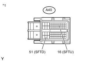
Text in Illustration *1 Front view of wire harness connector
(to ECM)
Disconnect the ECM connector.
-
Disconnect the transmission control switch (shift lock control unit assembly) connector.
-
Measure the resistance according to the value(s) in the table below.
Standard Resistance Tester Connection Switch Condition Specified Condition A40-16 (SFTU) - Body ground "+" shift paddle operated and held (up-shift) Below 2.5 Ω A40-51 (SFTD) - Body ground "-" shift paddle operated and held (down-shift) Below 2.5 Ω A40-16 (SFTU) - Body ground "+" shift paddle not operated (up-shift) 1 MΩ or higher A40-51 (SFTD) - Body ground "-" shift paddle not operated (down-shift) 1 MΩ or higher
NG
REPAIR OR REPLACE HARNESS OR CONNECTOR
OK
-
-
REPLACE ECM
-
Replace the ECM Click here.
NEXT
-
-
PERFORM INITIALIZATION
Note
-
Performing reset memory will clear the learned values of both the yaw rate sensor (deceleration sensor 0 point calibration) and CVT oil pressure (CVT oil pressure calibration). Make sure to perform reset memory, yaw rate sensor 0 point calibration and CVT oil pressure calibration when replacing any of the parts shown in the following table:
Replaced Part
-
Continuously variable transaxle assembly
-
ECM
-
Oil pressure sensor
-
Yaw rate sensor
-
-
After performing reset memory, always perform yaw rate sensor (deceleration sensor 0 point) calibration first, and then CVT oil pressure calibration.
-
Always perform 0 point calibration with the vehicle on level ground (Inclination: 0 +/-0.25°).
-
Do not shake or vibrate the vehicle during 0 point calibration.
-
Using the intelligent tester, perform reset memory, deceleration sensor 0 point calibration and CVT oil pressure calibration Click here.
-
Check that no DTC is stored.
NEXT
END
-