CONTINUOUSLY VARIABLE TRANSAXLE SYSTEM, Diagnostic DTC:P2767
| DTC Code | DTC Name |
|---|---|
| P2767 | Input / Turbine Speed Sensor "B" Circuit No Signal |
DESCRIPTION
The ECM detects the input shaft rotation speed based on the signal from the primary pulley speed sensor (transmission revolution sensor (NIN)) and performs gear ratio control.
| DTC Code | DTC Detection Condition
|
Trouble Area |
|---|---|---|
| P2767 |
|
|
MONITOR DESCRIPTION
The ECM receives a signal from the primary pulley speed sensor (transmission revolution sensor (NIN)) installed in the continuously variable transaxle and determines the input shaft speed in order to control the gear ratio. If the ECM detects no signal from the primary pulley speed sensor even while the vehicle is moving, it will conclude that there is a malfunction in the primary pulley speed sensor. The ECM will illuminate the MIL and store the DTC.
WIRING DIAGRAM
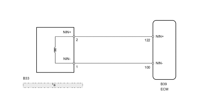
| *a | Transmission Revolution Sensor (NIN) |
PROCEDURE
-
READ VALUE USING INTELLIGENT TESTER (SPD (NIN))
-
Connect the intelligent tester to the DLC3.
-
Turn the ignition switch to ON.
-
Turn the intelligent tester on.
-
Enter the following menus: Powertrain / Engine and ECT / Data List.
-
In accordance with the display on the tester, read the Data List.
Engine and ECT Tester Display Measurement Item/Range Normal Condition Diagnostic Note SPD (NIN) Primary pulley speed (NIN)/
min.: 0 rpm
max.: 12750 rpm
-
Vehicle stopped: 0 rpm
-
Lock-up on (After warming up engine): Primary pulley speed (NIN) equal to engine speed
Data is displayed in increments of 50 rpm. Result Result Proceed to Data displayed is not as specified under Normal Condition A Data displayed is as specified under Normal Condition B -
B 
REPLACE ECM Click here
A 
-
-
INSPECT TRANSMISSION REVOLUTION SENSOR (NIN) (RESISTANCE)
-
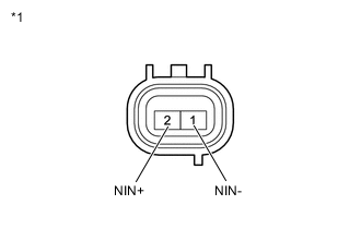
Text in Illustration *1 Component without harness connected
(Transmission Revolution Sensor (NIN))
Disconnect the transmission revolution sensor (NIN) connector.
-
Measure the resistance according to the value(s) in the table below.
Standard Resistance Tester Connection Condition Specified Condition 1 (NIN-) - 2 (NIN+) 20°C (68°F) 560 to 680 Ω
NG
INSPECT TRANSMISSION REVOLUTION SENSOR (NIN) (SENSOR TIP) Click here
OK
-
-
CHECK HARNESS AND CONNECTOR (TRANSMISSION REVOLUTION SENSOR (NIN) - ECM)
-
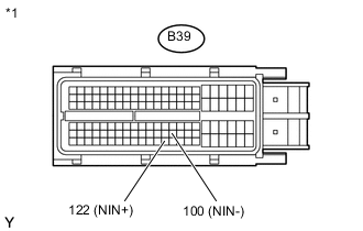
Text in Illustration *1 Front view of wire harness connector
(to ECM)
Disconnect the ECM connector.
-
Measure the resistance according to the value(s) in the table below.
Standard Resistance Tester Connection Condition Specified Condition B39-100 (NIN-) - B39-122 (NIN+) 20°C (68°F) 560 to 680 Ω B39-100 (NIN-) - Body ground Always 10 kΩ or higher B39-122 (NIN+) - Body ground Always 10 kΩ or higher
NG 
REPAIR OR REPLACE HARNESS OR CONNECTOR
OK
-
-
REPLACE ECM
-
Replace the ECM Click here.
NEXT
-
-
PERFORM INITIALIZATION
Note
-
Performing reset memory will clear the learned values of both the yaw rate sensor (deceleration sensor 0 point calibration) and CVT oil pressure (CVT oil pressure calibration). Make sure to perform reset memory, yaw rate sensor 0 point calibration and CVT oil pressure calibration when replacing any of the parts shown in the following table:
Replaced Part
-
Continuously variable transaxle assembly
-
ECM
-
Oil pressure sensor
-
Yaw rate sensor
-
-
After performing reset memory, always perform yaw rate sensor (deceleration sensor 0 point) calibration first, and then CVT oil pressure calibration.
-
Always perform 0 point calibration with the vehicle on level ground (Inclination: 0 +/-0.25°).
-
Do not shake or vibrate the vehicle during 0 point calibration.
-
Using the intelligent tester, perform reset memory, deceleration sensor 0 point calibration and CVT oil pressure calibration Click here.
-
Check that no DTC is stored.
NEXT
END
-
-
INSPECT TRANSMISSION REVOLUTION SENSOR (NIN) (SENSOR TIP)
-
Remove the transmission revolution sensor (NIN).
-
Check the sensor tip of the transmission revolution sensor (NIN).
OK The sensor tip of the transmission revolution sensor (NIN) is not damaged or contaminated. Tech Tips
If the sensor tip of the transmission revolution sensor (NIN) is damaged or contaminated with metal particles, the CVT belt may be damaged.
OK
REPLACE TRANSMISSION REVOLUTION SENSOR (NIN) Click here
NG
-
-
REPLACE CONTINUOUSLY VARIABLE TRANSAXLE ASSEMBLY
-
Replace the continuously variable transaxle assembly Click here.
NEXT
-
-
PERFORM INITIALIZATION
Note
-
Performing reset memory will clear the learned values of both the yaw rate sensor (deceleration sensor 0 point calibration) and CVT oil pressure (CVT oil pressure calibration). Make sure to perform reset memory, yaw rate sensor 0 point calibration and CVT oil pressure calibration when replacing any of the parts shown in the following table:
Replaced Part
-
Continuously variable transaxle assembly
-
ECM
-
Oil pressure sensor
-
Yaw rate sensor
-
-
After performing reset memory, always perform yaw rate sensor (deceleration sensor 0 point) calibration first, and then CVT oil pressure calibration.
-
Always perform 0 point calibration with the vehicle on level ground (Inclination: 0 +/-0.25°).
-
Do not shake or vibrate the vehicle during 0 point calibration.
-
Using the intelligent tester, perform reset memory, deceleration sensor 0 point calibration and CVT oil pressure calibration Click here.
-
Check that no DTC is stored.
NEXT
END
-