TRANSMISSION CONTROL CABLE INSTALLATION
PROCEDURE
-
INSTALL TRANSMISSION CONTROL CABLE ASSEMBLY
-
Install the control cable assembly through the floor hole.
-
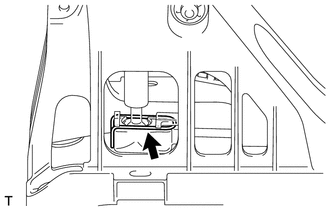
Attach the 2 claws to connect the shift control cable and select control cable to the floor shift lever assembly.
-
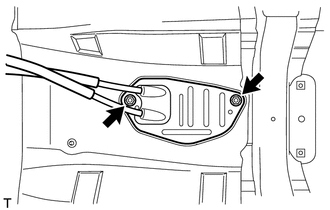
Attach the grommet of the control cable assembly with the 2 nuts.
- Torque:
- 5.0 N*m { 51 kgf*cm, 44 in.*lbf }
-
Connect the end of the shift control cable to the shift lever assembly and install the clip.
-
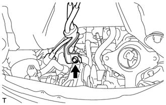
Attach the bracket of the control cable assembly with the bolt.
- Torque:
- 5.0 N*m { 51 kgf*cm, 44 in.*lbf }
-
Connect the 2 cables to the control cable bracket with 2 new clips.
-
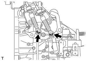
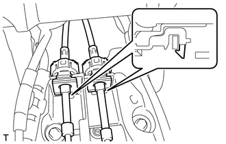
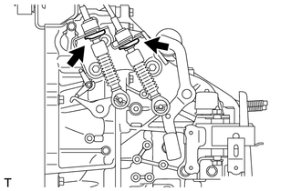
Connect the 2 cables to the transaxle and install the 2 clips.
-
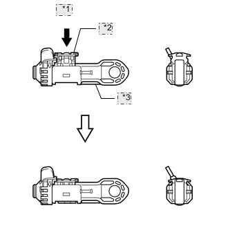
Release the lock of the cable length adjustment structure of the select cable.
-
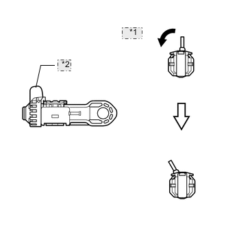
*1 Twist *2 Stopper Twist the stopper.
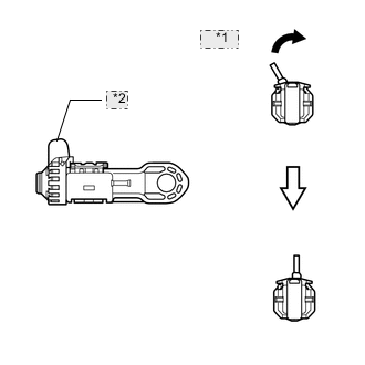
-
*1 Pull out *2 Lock Piece *3 Case Pull the lock piece outward from the case to release the lock.
-
-
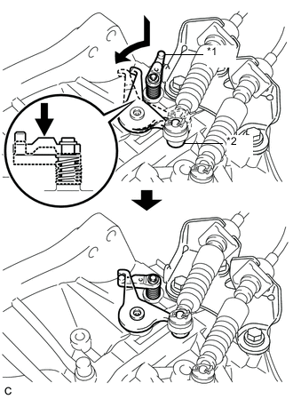
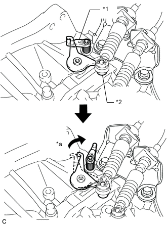
Text in Illustration *1 Reverse Restrict Pin Assembly *2 Outer Lever w/ Reverse Restrict Pin Assembly:
Hook the outer lever of the manual transaxle onto the reverse restrict pin assembly to secure it.
-
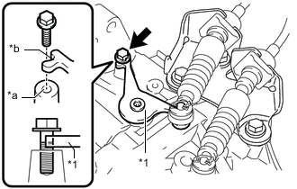
Text in Illustration *1 Outer Lever *a Installation hole for transmission control select cable adjustment *b Cutout w/o Reverse Restrict Pin Assembly:
Align the outer lever cutout with the hole for adjusting the transmission control select cable, and insert the bolt by hand to secure the outer lever as shown in the illustration.
Note
In order to avoid case damage, do not push the bolt in forcefully.
Tech Tips
-
Use a bolt with a diameter of 6.0 mm (0.236 in.) and a length of at least 18 mm (0.709 in.) or more.
-
Depending on the actual bolt diameter, it may be difficult to insert the bolt. In that case, as there is some variation in actual bolt diameters, use a 6.0 mm (0.236 in.) bolt with a comparatively small diameter.
-
-
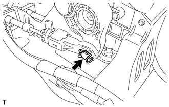
Connect the end of the select control cable to the shift lever assembly and install the clip.
Note
-
Make sure the lock piece of the select control cable is facing upward when the select control cable is connected.
-
Make sure the clip is inserted in the direction shown in the illustration.
-
-
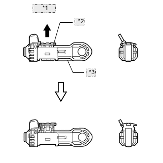
Text in Illustration *1 Slider *2 Inhibitor Wall Push the slider against the inhibitor wall.
Note
-
Do not pull up the slider.
-
When adjusting the cable, make sure that the shift lever is not in 1 or 2.
-
-
Lock the cable length adjustment structure of the select cable.
-
*1 Push *2 Lock Piece *3 Case Push the lock piece into the case with the slider held against the inhibitor wall.
-
*1 Return *2 Stopper Return the stopper to prevent the lock from being released.
Note
-
Push in the lock piece completely.
-
Make sure that the cable length adjustment structure is locked securely.
-
-
-
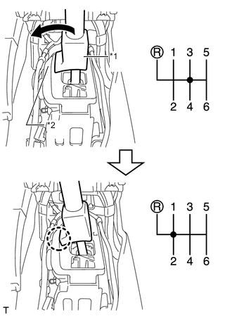
Text in Illustration *1 Reverse Restrict Pin Assembly *2 Outer Lever *a Release w/ Reverse Restrict Pin Assembly:
Move the shift lever to R to release the outer lever.
-
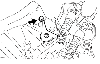
w/o Reverse Restrict Pin Assembly:
Pull out the bolt to free the outer lever.
-
-
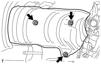
INSTALL FRONT NO. 1 FLOOR HEAT INSULATOR
-
Install the front No. 1 floor heat insulator with the 3 nuts.
- Torque:
- 5.5 N*m { 56 kgf*cm, 49 in.*lbf }
-
-
INSTALL CONSOLE BOX ASSEMBLY
-
INSTALL AIR CLEANER CASE SUB-ASSEMBLY
-
INSTALL AIR CLEANER CAP SUB-ASSEMBLY
-
INSTALL NO. 2 CYLINDER HEAD COVER
-
INSTALL FRONT EXHAUST PIPE ASSEMBLY