OUTPUT SHAFT INSPECTION

PROCEDURE
-
INSPECT 1ST GEAR THRUST CLEARANCE
-
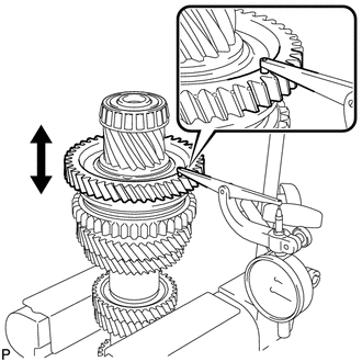
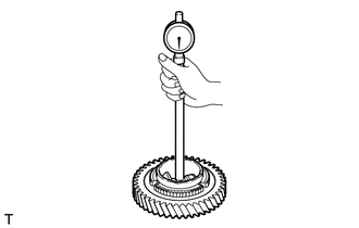
Using a dial indicator, measure the 1st gear thrust clearance.
Standard clearance 0.23 to 0.37 mm (0.00905 to 0.0146 in.) Maximum clearance 0.37 mm (0.0146 in.) If the clearance is more than the maximum, replace the No. 1 transmission clutch hub, 1st gear bush or 1st gear. Replace the part or parts determined to be the most likely cause of the problem.
-
-
INSPECT 2ND GEAR THRUST CLEARANCE
-
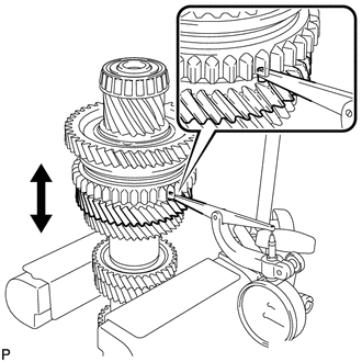
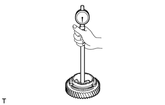
Using a dial indicator, measure the 2nd gear thrust clearance.
Standard clearance 0.16 to 0.33 mm (0.00629 to 0.0130 in.) Maximum clearance 0.33 mm (0.0130 in.) If the clearance is more than the maximum, replace the inner 2nd gear bearing race, No. 1 transmission clutch hub, 2nd gear or 3rd driven gear. Replace the part or parts determined to be the most likely cause of the problem.
-
-
INSPECT 1ST GEAR RADIAL CLEARANCE
-
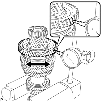
Using a dial indicator, measure the 1st gear radial clearance.
Standard clearance 0.009 to 0.047 mm (0.000354 to 0.00185 in.) Maximum clearance 0.047 mm (0.00185 in.) If the clearance is more than the maximum, replace the 1st gear, 1st gear needle roller bearing or output shaft. Replace the part or parts determined to be the most likely cause of the problem.
-
-
INSPECT 2ND GEAR RADIAL CLEARANCE
-
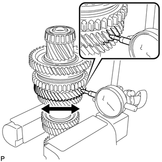
Using a dial indicator, measure the 2nd gear radial clearance.
Standard clearance 0.009 to 0.047 mm (0.000354 to 0.00185 in.) Maximum clearance 0.047 mm (0.00185 in.) If the clearance is more than the maximum, replace the 2nd gear, 2nd gear needle roller bearing or output shaft. Replace the part or parts determined to be the most likely cause of the problem.
-
-
INSPECT OUTPUT SHAFT
-
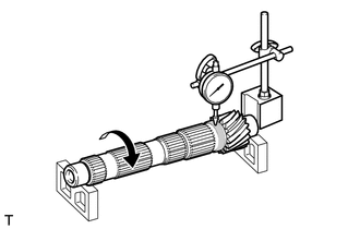
Using a dial indicator and 2 V-blocks, measure the output shaft runout.
Maximum runout 0.03 mm (0.00118 in.) If the runout is more than the maximum, replace the output shaft.
-
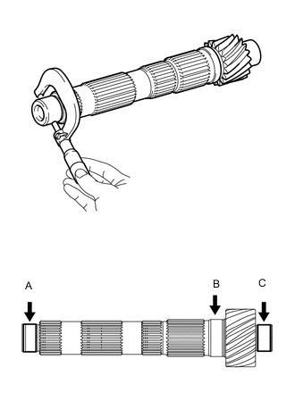
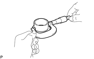
Using a micrometer, measure the outer diameter of the output shaft journal surface at the locations indicated.
Standard outer diameter Part A 28.010 to 28.023 mm (1.1027 to 1.1032 in.) Part B 42.180 to 42.200 mm (1.6606 to 1.6614 in.) Part C 36.010 to 36.026 mm (1.4177 to 1.4183 in.) Minimum outer diameter Part A 28.010 mm (1.1027 in.) Part B 42.180 mm (1.6606 in.) Part C 36.010 mm (1.4177 in.) If the outer diameter is less than the minimum, replace the output shaft.
-
-
INSPECT 1ST GEAR
-
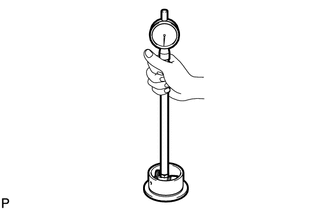
Using a cylinder gauge, measure the inside diameter of the 1st gear.
Standard inside diameter 57.909 to 57.925 mm (2.2798 to 2.2805 in.) Maximum inside diameter 57.925 mm (2.2805 in.) If the inside diameter is more than the maximum, replace the 1st gear.
-
-
INSPECT 2ND GEAR
-
Using a cylinder gauge, measure the inside diameter of the 2nd gear.
Standard inside diameter 57.909 to 57.925 mm (2.2798 to 2.805 in.) Maximum inside diameter 57.925 mm (2.2805 in.) If the inside diameter is more than the maximum, replace the 2nd gear.
-
-
INSPECT 1ST GEAR BUSH
-
Using a micrometer, measure the outer diameter of the 1st gear bush.
Standard outer diameter 51.89 to 51.90 mm (2.0429 to 2.0433 in.) Minimum outer diameter 51.89 mm (2.0429 in.) If the outer diameter is less than the minimum, replace the 1st gear bush.
-
Using a cylinder gauge, measure the inside diameter of the 1st gear bush.
Standard inside diameter 42.200 to 42.215 mm (1.6614 to 1.6620 in.) Maximum inside diameter 42.215 mm (1.6620 in.) If the inside diameter is more than the maximum, replace the 1st gear bush.
-
-
INSPECT INNER 2ND GEAR BEARING RACE
-
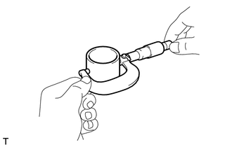
Using a micrometer, measure the outer diameter of the inner 2nd gear bearing race.
Standard outer diameter 51.89 to 51.90 mm (2.0429 to 2.0433 in.) Minimum outer diameter 51.89 mm (2.0429 in.) If the outer diameter is less than the minimum, replace the inner 2nd gear bearing race.
-
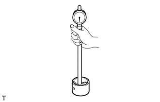
Using a cylinder gauge, measure the inside diameter of the inner 2nd gear bearing race.
Standard inside diameter 42.200 to 42.215 mm (1.6614 to 1.6620 in.) Maximum inside diameter 42.215 mm (1.6620 in.) If the inside diameter is more than the maximum, replace the inner 2nd gear bearing race.
-
-
INSPECT NO. 1 SYNCHRONIZER RING SET (for 1st Gear)
-
Coat the 1st gear cone and No. 1 synchronizer ring set (inner ring, middle ring and outer ring) with gear oil.
-
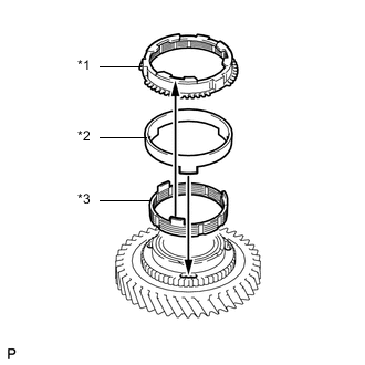
Text in Illustration *1 Outer Ring *2 Middle Ring *3 Inner Ring Install the inner ring to the 1st gear.
-
Install the middle ring to the 1st gear.
-
Install the outer ring to the 1st gear.
-
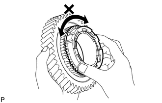
Check for wear and damage.
-
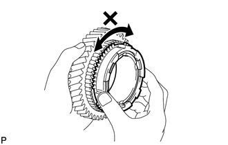
Turn the synchronizer ring in both directions while pushing it against the 1st gear cone and check that it locks in both directions.
If the synchronizer ring does not lock, replace the synchronizer ring.
-
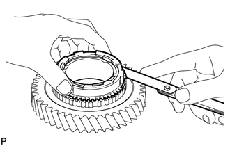
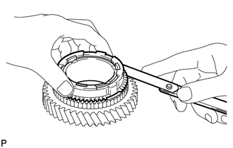
Using a feeler gauge, measure the clearance between the synchronizer ring set and gear spline end.
Standard clearance 0.88 to 1.72 mm (0.0346 to 0.0677 in.) Minimum clearance 0.88 mm (0.0346 in.) If the clearance is less than the minimum, replace the synchronizer ring set.
-
-
INSPECT NO. 1 SYNCHRONIZER RING SET (for 2nd Gear)
-
Coat the 2nd gear cone and No. 1 synchronizer ring set (inner ring, middle ring and outer ring) with gear oil.
-
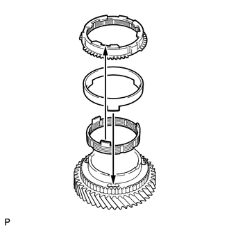
Install the inner ring to the 2nd gear.
-
Install the middle ring to the 2nd gear.
-
Install the outer ring to the 2nd gear.
-
Check for wear and damage.
-
Turn the synchronizer ring in both directions while pushing it against the 2nd gear cone and check that it locks in both directions.
If the synchronizer ring does not lock, replace the synchronizer ring.
-
Using a feeler gauge, measure the clearance between the synchronizer ring set and gear spline end.
Standard clearance 0.88 to 1.72 mm (0.0346 to 0.0677 in.) Minimum clearance 0.88 mm (0.0346 in.) If the clearance is less than the minimum, replace the synchronizer ring set.
-
-
INSPECT REVERSE GEAR
-
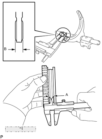
*1 Clearance = A - B Using a vernier caliper, measure the width of the reverse gear groove (A) and the thickness of the claw part on the No. 1 gear shift fork shaft assembly (B), and calculate the clearance.
Standard clearance (A - B) 0.1 to 0.5 mm (0.00394 to 0.0196 in.) If the clearance is not as specified, replace the reverse gear and No. 1 gear shift fork shaft assembly.
-
-
INSPECT NO. 1 TRANSMISSION CLUTCH HUB
-
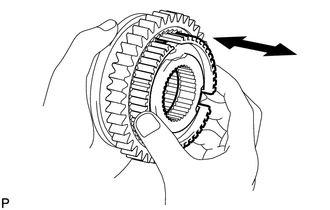
Check that the No. 1 transmission clutch hub and reverse gear slide smoothly.
-
Check that the edges of the reverse gear spline gear are not worn down.
-