AUTOMATIC TRANSAXLE ASSEMBLY INSTALLATION
PROCEDURE
-
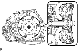
INSTALL TORQUE CONVERTER ASSEMBLY
-
Mesh the splines of the input shaft and turbine runner.
-
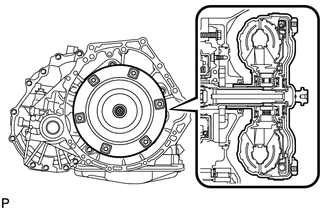
Mesh the splines of the stator shaft and stator while turning torque converter.
Tech Tips
If the stator shaft splines are difficult to mesh with the stator splines, move the torque converter back approximately 10 mm (0.394 in.) and mesh the splines while rotating the torque converter.
-
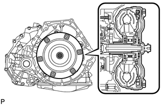
Turn the torque converter to insert the key of the oil pump drive gear into the slot on the torque converter.
-
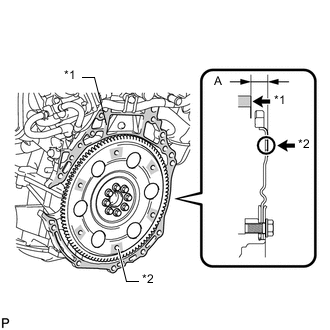
Using a vernier caliper and straightedge, measure dimension A between the transaxle fitting surface of the engine*1 and the converter clutch fitting surface of the drive plate*2. (#)
-
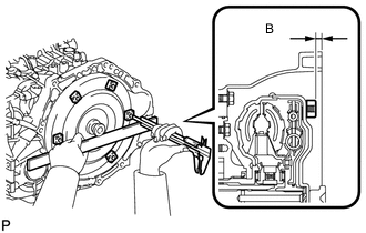
Using a vernier caliper and straightedge, measure dimension B shown in the illustration. Check that B is greater than A (measured in (#)).
Standard dimension A + 1.0 mm (0.0394 in.) or more Note
-
Be sure to subtract the thickness of the straightedge.
-
If the transaxle is installed to the engine with the torque converter not sufficiently inserted, the torque converter may be damaged.
-
-
-
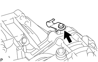
INSTALL TRANSMISSION CONTROL CABLE SUPPORT
-
Install the transmission control cable support with the bolt.
- Torque:
- 5.0 N*m { 51 kgf*cm, 44 in.*lbf }
-
-
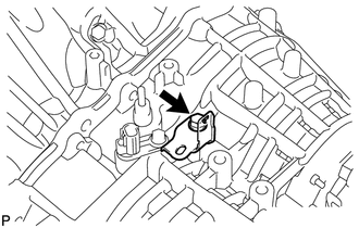
INSTALL WIRE HARNESS CLAMP BRACKET
-
Install the bracket with the bolt.
- Torque:
- 13 N*m { 130 kgf*cm, 9 ft.*lbf }
-
-
INSTALL SPEEDOMETER DRIVEN HOLE COVER SUB-ASSEMBLY
-
Coat a new O-ring with ATF WS and install it to the hole cover.
-
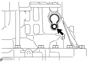
Install the hole cover to the transaxle case with the bolt.
- Torque:
- 5.5 N*m { 56 kgf*cm, 49 in.*lbf }
-
-
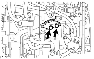
INSTALL NO. 1 TRANSMISSION CONTROL CABLE BRACKET
-
Install the No. 1 transmission control cable bracket with the 2 bolts.
- Torque:
- 12 N*m { 122 kgf*cm, 9 ft.*lbf }
-
-
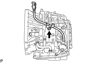
INSTALL TRANSMISSION OIL FILLER TUBE SUB-ASSEMBLY
-
Coat a new O-ring with ATF WS and install it to the oil filler tube sub-assembly.
-
Install the oil filler tube to the automatic transaxle with the bolt.
- Torque:
- 5.5 N*m { 56 kgf*cm, 49 in.*lbf }
-
Install the ATF dipstick.
-
-
INSTALL AUTOMATIC TRANSAXLE ASSEMBLY
-
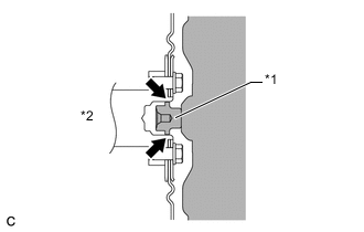
Apply clutch spline grease to the round of the crankshaft contact surface with the torque converter centerpiece.
Text in Illustration *1 Torque Convertor Centerpiece *2 Crankshaft Clutch spline grease Toyota Genuine Clutch Spline Grease or equivalent Maximum spread About 1 g (0.0353 oz) -
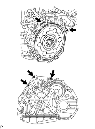
Install the automatic transaxle to the engine with the 3 bolts.
- Torque:
- 38 N*m { 387 kgf*cm, 28 ft.*lbf }
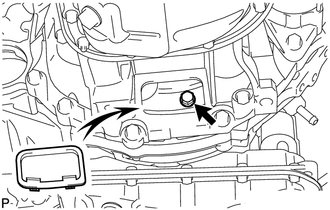
Note
Confirm that 2 knock pins are on the transaxle fitted surface of the engine block before transaxle installation.
-
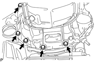
Install the 5 lower side mounting bolts.
- Torque:
- 38 N*m { 387 kgf*cm, 28 ft.*lbf }
-
-
INSTALL DRIVE PLATE AND TORQUE CONVERTER SETTING BOLT
-
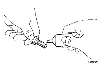
Apply a few drops of adhesive to 2 or 3 threads of the 6 torque converter setting bolts tips.
Adhesive Toyota Genuine Adhesive 1324, Three Bond 1324 or equivalent -
Turn the crankshaft to gain access to the installation locations of the 6 torque converter setting bolts and install each bolt while holding the crankshaft pulley bolt with a wrench.
- Torque:
- 41 N*m { 418 kgf*cm, 30 ft.*lbf }
Note
Install the black bolt first, and then the 5 silver bolts.
-
Install the flywheel housing under cover.
-
-
INSTALL OIL COOLER TUBE SUB-ASSEMBLY
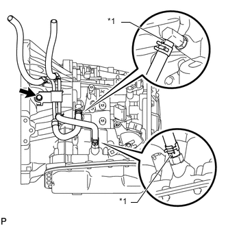
Text in Illustration *1 Yellow Paint Mark
-
Install the oil cooler tube with the bolt and connect the 2 oil cooler hoses.
- Torque:
- 12 N*m { 117 kgf*cm, 8 ft.*lbf }
Note
Make sure the paint marks and pinching portion of each clip are facing the direction shown in the illustration.
-
-
INSTALL ENGINE MOUNTING BRACKET LH
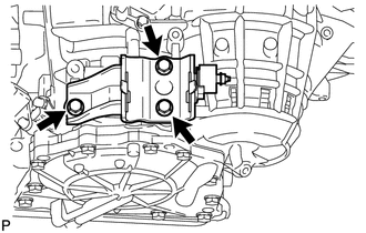
-
Install the mounting bracket to the automatic transaxle with the 3 bolts.
- Torque:
- 64 N*m { 653 kgf*cm, 47 ft.*lbf }
-
-
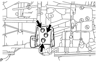
INSTALL REAR ENGINE MOUNTING BRACKET
-
Install the mounting bracket to the automatic transaxle with the 3 bolts.
- Torque:
- 45 N*m { 459 kgf*cm, 33 ft.*lbf }
-
-
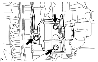
INSTALL FRONT ENGINE MOUNTING BRACKET
-
Install the mounting bracket to the automatic transaxle with the 3 bolts.
- Torque:
- 64 N*m { 653 kgf*cm, 47 ft.*lbf }
-
-
INSTALL GROUND CABLE
-
Install the ground cable with the bolt and attach the harness clamp.
- Torque:
- 26 N*m { 260 kgf*cm, 19 ft.*lbf }
-
-
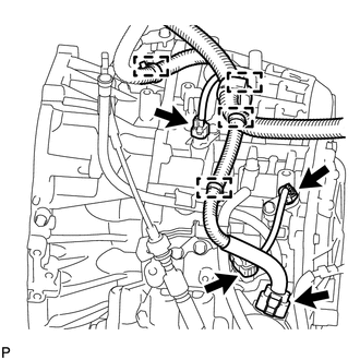
CONNECT WIRE HARNESS
-
Connect the 2 speed sensor connectors.
-
Connect the transaxle wire connector.
-
Connect the park/neutral position switch connector.
-
Attach the 4 wire harness clamps.
-
-
INSTALL STARTER ASSEMBLY
-
INSTALL ENGINE ASSEMBLY WITH TRANSAXLE
-
Install the engine assembly with transaxle Click here.
-
-
ADD AUTOMATIC TRANSAXLE FLUID
Fluid type Toyota Genuine ATF WS -
INSPECT TRANSAXLE FLUID LEVEL
-
Inspect the transaxle fluid level Click here.
-
-
INSPECT SHIFT LEVER POSITION
-
ADJUST SHIFT LEVER POSITION
-
RESET MEMORY
Tech Tips
Perform Reset Memory (AT initialization) when replacing the automatic transaxle assembly Click here.