PARK / NEUTRAL POSITION SWITCH INSTALLATION
PROCEDURE
-
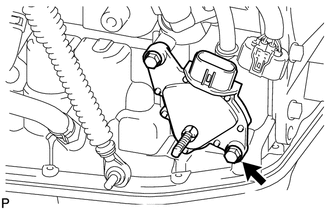
INSTALL PARK/NEUTRAL POSITION SWITCH ASSEMBLY
-
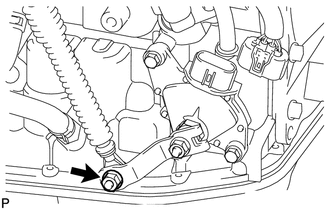
Install the park/neutral position switch to the manual valve shaft.
-
Temporarily install the 2 bolts.
-
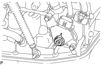
Install a new lock plate and the lock nut.
- Torque:
- 6.9 N*m { 70 kgf*cm, 61 in.*lbf }
-
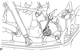
Temporarily install the control shaft lever.
-
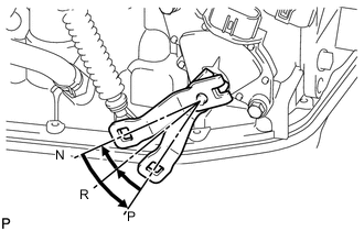
Turn the lever counterclockwise until it stops, and then turn it clockwise 2 notches.
-
Remove the control shaft lever.
-
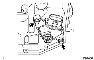
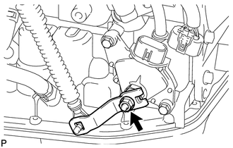
Text in Illustration *1 Neutral Basic Line *2 Protrusion Align the groove with the neutral basic line.
-
Hold the switch in this position and tighten the 2 bolts.
- Torque:
- 5.4 N*m { 55 kgf*cm, 48 in.*lbf }
-
Using a screwdriver, bend the tabs of the lock plate.
-
Install the control shaft lever with the washer and nut.
- Torque:
- 13 N*m { 130 kgf*cm, 9 ft.*lbf }
-
-
CONNECT TRANSMISSION CONTROL CABLE ASSEMBLY
-
Connect the transmission control cable to the control shaft lever with the nut.
- Torque:
- 12 N*m { 122 kgf*cm, 9 ft.*lbf }
-
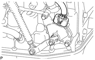
Connect the park/neutral position switch connector.
-
-
INSTALL BATTERY CARRIER
-
INSTALL BATTERY
-
CONNECT CABLE TO NEGATIVE BATTERY TERMINAL
Note
When disconnecting the cable, some systems need to be initialized after the cable is reconnected Click here.
-
INSTALL RADIATOR SUPPORT OPENING COVER
-
INSPECT SHIFT LEVER POSITION
-
ADJUST SHIFT LEVER POSITION
-
INSPECT PARK/NEUTRAL POSITION SWITCH ASSEMBLY