AUTOMATIC TRANSAXLE SYSTEM Transmission Control Switch Circuit
DESCRIPTION
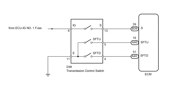
After moving the shift lever to S, it is possible to switch the range between "1" (S1 range) and "4" (S4 range) using the transmission control switch.
Moving the shift lever to "+" once raises the range by one, and moving the shift lever to "-" lowers the range by one.
WIRING DIAGRAM
PROCEDURE
-
INSPECT TRANSMISSION CONTROL SWITCH
-
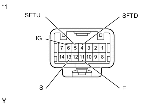
Text in Illustration *1 Component without harness connected
(Transmission Control Switch)
Disconnect the D49 transmission control switch connector.
-
Measure the resistance according to the value(s) in the table below.
Standard Resistance Tester Connection Condition Specified Condition 6 (IG) - 13 (S) Shift lever in S, "+" or "-" Below 1 Ω 5 (SFTU) - 11 (E) Shift lever held in "+" (Up-shift) Below 1 Ω 4 (SFTD) - 11(E) Shift lever held in "-" (Down-shift) Below 1 Ω 6 (IG) - 13 (S) Shift lever not in S, "+" or "-" 10 kΩ or higher 5 (SFTU) - 11 (E) Shift lever in S 10 kΩ or higher 4 (SFTD) - 11 (E) Shift lever in S 10 kΩ or higher
NG 
REPLACE TRANSMISSION CONTROL SWITCH (SHIFT LOCK CONTROL UNIT ASSEMBLY) Click here
OK 
-
-
CHECK HARNESS AND CONNECTOR (TRANSMISSION CONTROL SWITCH - BATTERY, BODY GROUND)
-
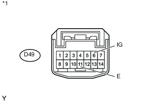
Text in Illustration *1 Front view of wire harness connector
(to Transmission Control Switch)
Disconnect the D49 transmission control switch connector.
-
Measure the voltage according to the value(s) in the table below.
Standard Voltage Tester Connection Switch Condition Specified Condition D49-6 (IG) - Body ground Ignition switch ON 11 to 14 V D49-6 (IG) - Body ground Ignition switch off Below 1 V -
Turn the ignition switch off.
-
Measure the resistance according to the value(s) in the table below.
Standard Resistance Tester Connection Condition Specified Condition D49-11 (E) - Body ground Always Below 1 Ω
NG
REPAIR OR REPLACE HARNESS OR CONNECTOR
OK
-
-
CHECK HARNESS AND CONNECTOR (TRANSMISSION CONTROL SWITCH - ECM)
-
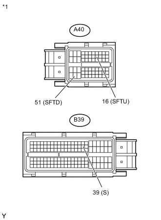
Text in Illustration *1 Front view of wire harness connector
(to ECM)
Disconnect the A40 and B39 ECM connectors.
-
Measure the voltage according to the value(s) in the table below.
Standard Voltage Tester Connection Condition Specified Condition B39-39 (S) - Body ground
-
Ignition switch ON
-
Shift lever in S, "+" or "-"
11 to 14 V B39-39 (S) - Body ground
-
Ignition switch ON
-
Shift lever not in S, "+" or "-"
Below 1 V -
-
Turn the ignition switch off.
-
Measure the resistance according to the value(s) in the table below.
Standard Resistance Tester Connection Condition Specified Condition A40-16 (SFTU) - Body ground Shift lever held in "+" (Up-shift) Below 1 Ω A40-51 (SFTD) - Body ground Shift lever held in "-" (Down-shift) Below 1 Ω A40-16 (SFTU) - Body ground Shift lever in S 10 kΩ or higher A40-51 (SFTD) - Body ground Shift lever in S 10 kΩ or higher
OK
PROCEED TO NEXT SUSPECTED AREA SHOWN IN PROBLEM SYMPTOMS TABLE Click here
NG
REPAIR OR REPLACE HARNESS OR CONNECTOR
-