CONTINUOUSLY VARIABLE TRANSAXLE SYSTEM, Diagnostic DTC:P099B, P099C
| DTC Code | DTC Name |
|---|---|
| P099B | Shift Solenoid "G" Control Circuit Low (Shift Solenoid Valve SC) |
| P099C | Shift Solenoid "G" Control Circuit High (Shift Solenoid Valve SC) |
DESCRIPTION
Based on the signal received by the shift solenoid valve SC, the ECM uses the shift solenoid valve SLU to control the forward and reverse clutch pressure.
If there is an open or short in the shift solenoid valve SC circuit, the ECM stops sending current to the defective shift solenoid valve.
| DTC No. | DTC Detection Condition
|
Trouble Area |
|---|---|---|
| P099B |
|
|
| P099C |
|
|
MONITOR DESCRIPTION
These DTCs indicate an open or short in the shift solenoid valve SC circuit. If there is an open or short in the shift solenoid valve SC circuit, the ECM detects the problem and stores a DTC.
WIRING DIAGRAM
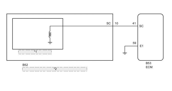
| *1 | Shift Solenoid Valve SC |
| *2 | Continuously Variable Transaxle Assembly (Transmission Wire) |
CAUTION / NOTICE / HINT
Note
-
Perform initialization when parts related to the continuously variable transaxle are replaced Click here.
-
Check that no DTCs are stored after performing initialization Click here.
PROCEDURE
-
INSPECT TRANSMISSION WIRE (SHIFT SOLENOID VALVE SC)
-
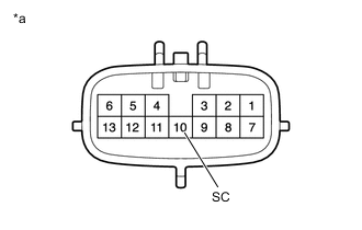
Text in Illustration *a Component without harness connected
(Transmission Wire)
Disconnect the transmission wire connector.
-
Measure the resistance according to the value(s) in the table below.
Standard Resistance Tester Connection Condition Specified Condition 10 (SC) - Body ground 20°C (68°F) 11 to 15 Ω
NG 
REPLACE CONTINUOUSLY VARIABLE TRANSAXLE ASSEMBLY Click here
OK 
-
-
CHECK HARNESS AND CONNECTOR (TRANSMISSION WIRE - ECM)
-
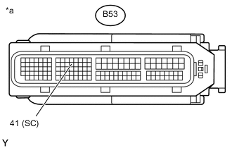
Text in Illustration *a Front view of wire harness connector
(to ECM)
Disconnect the ECM connector
-
Measure the resistance according to the value(s) in the table below.
Standard Resistance Tester Connection Condition Specified Condition B53-41 (SC) - Body ground 20°C (68°F) 11 to 15 Ω
NG 
REPAIR OR REPLACE HARNESS OR CONNECTOR (TRANSMISSION WIRE - ECM)
OK
-
-
REPLACE ECM
-
Replace the ECM Click here.
NEXT
PERFORM INITIALIZATION Click here
-
-
REPLACE CONTINUOUSLY VARIABLE TRANSAXLE ASSEMBLY
-
Replace the continuously variable transaxle assembly Click here.
NEXT
PERFORM INITIALIZATION Click here
-