РАСПРЕДВАЛ УСТАНОВКА

-
INSTALL CAMSHAFT
-
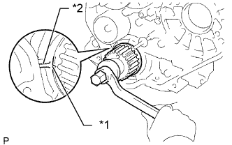
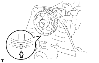
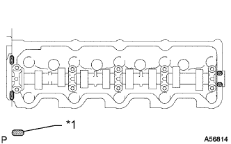
Text in Illustration *1 Timing Mark *2 Protrusion Check that the timing mark of the crankshaft timing pulley is in the position shown in the illustration.
-
Install the camshaft.
-
Place the camshaft on the cylinder head with the key groove facing upward.
-
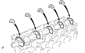
Install the 5 bearing caps in their proper locations.
-
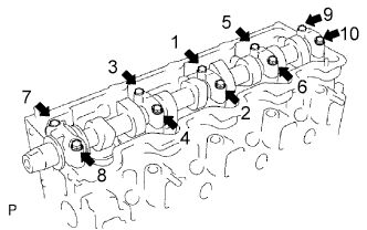
Apply a light coat of engine oil to the threads and under the heads of the bearing cap bolts.
-
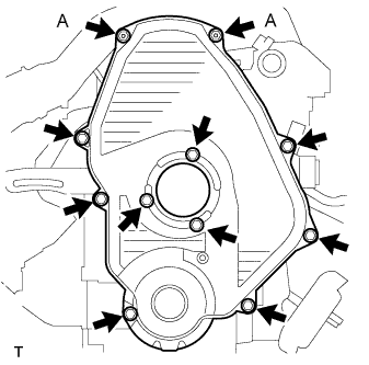
Install and uniformly tighten the 10 bearing cap bolts in several steps in the sequence shown in the illustration.
- Torque:
- 25 N*m { 255 kgf*cm, 18 ft.*lbf }
-
-
-
INSTALL CAMSHAFT OIL SEAL
-
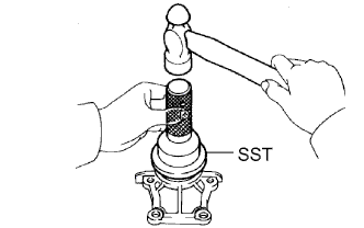
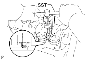
Using SST and a hammer, tap in a new oil seal until its surface is flush with the oil seal retainer edge.
- SST
- 09960-10010 ( 09962-01000, 09963-01000 )
-
Apply MP grease to the lip of the oil seal.
-
-
INSTALL CAMSHAFT OIL SEAL RETAINER
-
Install a new gasket and the retainer with the 4 bolts.
- Torque:
- 18 N*m { 184 kgf*cm, 13 ft.*lbf }
-
-
INSTALL NO. 2 TIMING BELT COVER
-
Install the timing belt cover with the 4 bolts.
- Torque:
- 18 N*m { 184 kgf*cm, 13 ft.*lbf }
-
-
INSTALL CAMSHAFT TIMING PULLEY
-
Install the woodruff key to the key groove of the camshaft.
-
Align the timing mark on the camshaft timing pulley with the timing mark on the No. 2 timing belt cover and temporarily install the pulley with the bolt.
-
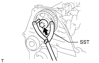
Using SST, tighten the bolt.
- SST
- 09960-10010 ( 09962-01000, 09963-01000 )
- Torque:
- 98 N*m { 999 kgf*cm, 72 ft.*lbf }
-
-
SET NO. 1 CYLINDER TO TDC/COMPRESSION
-
Text in Illustration *1 Timing Mark 
Turn Using the crankshaft pulley bolt, align the groove of the crankshaft pulley with the timing pointer by turning the crankshaft clockwise.
Note
Do not turn the crankshaft pulley counterclockwise.
-
Set the timing and drive pulleys at each position.
Note
-
Make sure the engine is cold.
-
When turning the crankshaft or camshaft, the valve heads will hit against the piston top. Do not turn them more than necessary.
-
-
-
INSTALL TIMING BELT
Tech Tips
If reusing the timing belt, align the points marked during removal, and install the timing belt with the arrow pointing in the direction the belt moves when the engine is running.
-
Remove any oil or water on each pulley, and keep them clean.
-
Install the timing belt to the crankshaft timing and timing belt idlers.
-
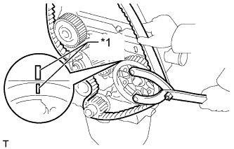
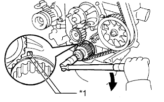
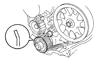
Text in Illustration *1 Timing Mark Using SST, slightly turn the injection pump drive pulley clockwise. Install the timing belt to the pulley, and align the timing marks of the drive pulley and timing belt case.
- SST
- 09960-10010 ( 09962-01000, 09963-01000 )
-
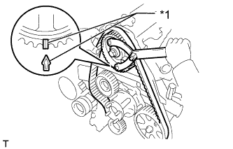
Text in Illustration *1 Timing Mark Using SST, slightly turn the camshaft timing pulley clockwise. Install the timing belt to the timing pulley, and align the timing marks of the timing pulley and timing belt case.
- SST
- 09960-10010 ( 09962-01000, 09963-01000 )
-
Check that the timing belt has tension between the injection pump drive and camshaft timing pulleys.
-
Install the timing belt to the No. 1 timing belt idler.
-
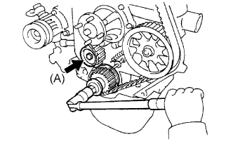
Loosen the No. 1 timing belt idler bolt (A), and stretch the timing belt.
-
Slowly turn the crankshaft pulley.
Note
Always turn the crankshaft clockwise.
-
Tighten the No. 1 timing belt idler bolt.
- Torque:
- 44 N*m { 449 kgf*cm, 33 ft.*lbf }
-
-
CHECK NO. 1 CYLINDER TO TDC/COMPRESSION
-
Slowly turn the crankshaft pulley 2 revolutions from TDC to TDC.
Note
Always turn the crankshaft clockwise.
-
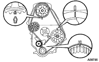
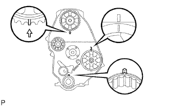
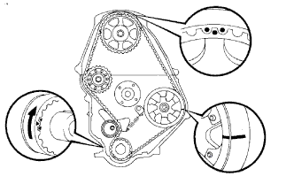
Check that the timing marks for each pulley align as shown in the illustration.
If the timing marks do not align, remove the timing belt and reinstall it.
-
-
INSTALL TIMING BELT GUIDE
-
Install the timing belt guide with the cup side facing outward.
-
-
INSPECT VALVE CLEARANCE
-
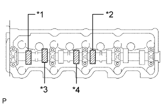
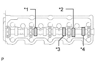
Text in Illustration *1 No. 1 EX *2 No. 3 EX *3 No. 1 IN *4 No. 2 IN Check only the valves indicated in the illustration.
-
Using a feeler gauge, measure the clearance between the valve lifter and camshaft.
Standard Valve Clearance (Cold) Item Specified Condition Intake 0.20 to 0.30 mm (0.00787 to 0.0118 in.) Exhaust 0.40 to 0.50 mm (0.0158 to 0.0197 in.) -
Record the out-of-specification valve clearance measurements. They will be used later to determine the required replacement adjusting shim.
-
-
Turn the crankshaft 1 revolution (360°) and align the mark as above.
-
Text in Illustration *1 No. 2 EX *2 No. 4 EX *3 No. 3 IN *4 No. 4 IN Check only the valves indicated in the illustration.
-
Using a feeler gauge, measure the clearance between the valve lifter and camshaft.
Standard Valve Clearance (Cold) Item Specified Condition Intake 0.20 to 0.30 mm (0.00787 to 0.0118 in.) Exhaust 0.40 to 0.50 mm (0.0158 to 0.0197 in.) -
Record the out-of-specification valve clearance measurements. They will be used later to determine the required replacement adjusting shim.
-
-
-
ADJUST VALVE CLEARANCE
-
Remove the adjusting shim.
-
Turn the crankshaft so that the cam lobe of the camshaft on the valve being adjusted points upward.
-
Using SST, press down the valve lifter.
- SST
- 09248-64011
-
Position the notch of the valve lifter so that it faces the exhaust manifold side.
-
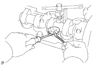
Remove the adjusting shim with a screwdriver and magnet hand.
-
-
Determine the replacement adjusting shim size according to the formula and charts below.
-
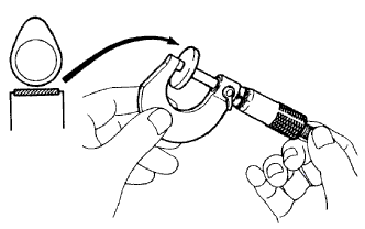
Using a micrometer, measure the thickness of the removed shim.
-
Calculate the thickness of a new shim so that the valve clearance comes within the specified value.
T = Thickness of removed shim
A = Measured valve clearance
N = Thickness of new shim
Intake N = T + (A - 0.25 mm (0.00984 in.)) Exhaust N = T + (A - 0.45 mm (0.0177 in.)) -
Select a new shim with a thickness as close as possible to the calculated value.
Tech Tips
Shims are available in 17 sizes in increments of 0.05 mm (0.00197 in.), from 2.50 mm (0.0984 in.) to 3.30 mm (0.130 in.).
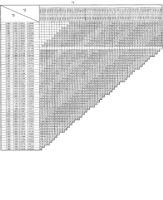
Text in Illustration *1 Adjusting Shim Selection Chart (Intake) *2 Removed shim thickness mm (in.) *3 Measure clearance mm (in.) - - New Shim Thickness mm (in.) Shim No. Thickness Shim No. Thickness 01 2.50 (0.0984) 46 2.95 (0.116) 42 2.55 (0.100) 26 3.00 (0.118) 06 2.60 (0.102) 47 3.05 (0.120) 43 2.65 (0.104) 31 3.10 (0.122) 11 2.70 (0.106) 48 3.15 (0.124) 44 2.75 (0.108) 36 3.20 (0.126) 16 2.80 (0.110) 49 3.25 (0.128) 45 2.85 (0.112) 41 3.30 (0.130) 21 2.90 (0.114) Intake valve clearance (Cold) 0.20 to 0.30 mm (0.00787 to 0.0118 in.) EXAMPLE:
A 2.80 mm (0.110 in.) shim is installed and the measured clearance is 0.350 mm (0.0138 in.). Replace the 2.80 mm (0.110 in.) shim with a No. 21 shim.
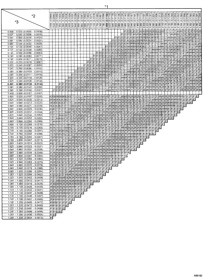
Text in Illustration *1 Adjusting Shim Selection Chart (Exhaust) *2 Removed Shim Thickness mm (in.) *3 Measure Clearance mm (in.) - - New Shim Thickness mm (in.) Shim No. Thickness Shim No. Thickness 01 2.50 (0.0984) 46 2.95 (0.116) 42 2.55 (0.100) 26 3.00 (0.118) 06 2.60 (0.102) 47 3.05 (0.120) 43 2.65 (0.104) 31 3.10 (0.122) 11 2.70 (0.106) 48 3.15 (0.124) 44 2.75 (0.108) 36 3.20 (0.126) 16 2.80 (0.110) 49 3.25 (0.128) 45 2.85 (0.112) 41 3.30 (0.130) 21 2.90 (0.114) Exhaust valve clearance (Cold) 0.40 to 0.50 mm (0.0157 to 0.0196 in.) EXAMPLE:
A 2.80 mm (0.110 in.) shim is installed and the measured clearance is 0.350 mm (0.0138 in.). Replace the 2.80 mm (0.110 in.) shim with a No. 11 shim.
-
-
Install a new adjusting shim.
-
Install a new adjusting shim to the valve lifter.
-
Remove SST.
-
-
Recheck valve clearance.
-
-
INSTALL CYLINDER HEAD COVER SUB-ASSEMBLY
-
Remove any old packing (FIPG material).
-
Text in Illustration *1 Seal Packing Apply seal packing to the cylinder head as shown in the illustration.
Seal packing Toyota Genuine Seal Packing Black, Three Bond 1207B or equivalent -
Install the gasket to the cylinder head cover.
-
Install the cylinder head cover with the 9 bolts and nut. Uniformly tighten the bolts and nut in several steps.
- Torque:
- 12 N*m { 122 kgf*cm, 9 ft.*lbf }
-
-
INSTALL INTAKE PIPE
-
Install the intake pipe with the 2 bolts.
- Torque:
- 18 N*m { 184 kgf*cm, 13 ft.*lbf }
-
Tighten the intake pipe clamp.
- Torque:
- 6.0 N*m { 61 kgf*cm, 53 in.*lbf }
-
-
INSTALL TIMING BELT COVER
-
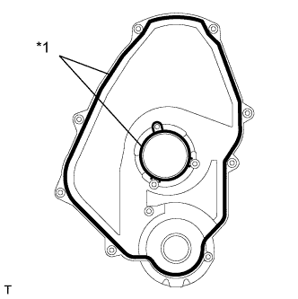
Text in Illustration *1 Gasket Install 2 new gaskets to the timing belt cover.
-
Install the timing belt cover with the 11 bolts and washers.
- Torque:
- for bolt A
- 8.5 N*m { 85 kgf*cm, 75 ft.*lbf }
- except bolt A
- 11 N*m { 107 kgf*cm, 8 ft.*lbf }
-
-
INSTALL IDLE PULLEY ASSEMBLY
-
Install the idle pulley bracket with the 2 bolts.
- Torque:
- 29 N*m { 300 kgf*cm, 22 ft.*lbf }
-
-
INSTALL CRANKSHAFT PULLEY
-
Align the key groove of the pulley with the pulley set key, and slide the pulley onto the crankshaft to install it.
-
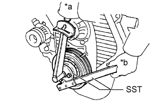
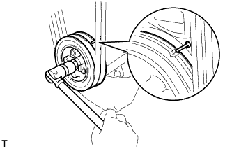
Text in Illustration *a Turn *b Hold Using SST, install the pulley bolt.
- SST
- 09213-54015 ( 91651-60855 )
- 09330-00021
- Torque:
- 235 N*m { 2396 kgf*cm, 173 ft.*lbf }
-
-
INSTALL VANE PUMP DRIVE PULLEY
-
Install the vane pump drive pulley and cooler compressor drive pulley with the 4 bolts.
- Torque:
- 19 N*m { 194 kgf*cm, 14 ft.*lbf }
-
-
INSTALL FAN SHROUD
-
Install the fan pulley to the water pump.
-
Install the shroud together with the coupling fan between the radiator and engine.
Note
Be careful not to damage the radiator core.
-
Temporarily install the fluid coupling fan to the fan pulley with the 4 nuts. Tighten the nuts as much as possible by hand.
-
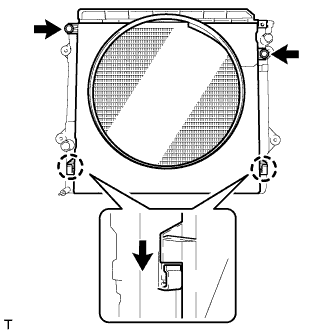
Attach the claws of the shroud as shown in the illustration.
-
Install the shroud with the 2 bolts.
- Torque:
- 5.0 N*m { 51 kgf*cm, 44 in.*lbf }
-
Install the fan and generator V belt and vane pump V belt Click here.
-
Tighten the 4 nuts of the fluid coupling fan.
- Torque:
- 19 N*m { 189 kgf*cm, 14 ft.*lbf }
-
-
INSTALL RADIATOR RESERVE TANK ASSEMBLY
-
Install the radiator reservoir with the 3 bolts.
- Torque:
- 5.0 N*m { 51 kgf*cm, 44 in.*lbf }
-
Connect the radiator reservoir hose to the radiator tank side.
-
-
INSTALL NO. 1 RADIATOR HOSE
-
Install the hose clamp with the 2 nuts.
- Torque:
- 8.5 N*m { 87 kgf*cm, 75 in.*lbf }
-
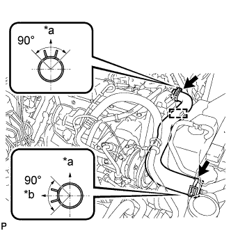
Text in Illustration *a Upper *b RH Side Install the radiator hose.
Tech Tips
Position the hose clamps as shown in the illustration.
-
-
INSTALL WIRING HARNESS CLAMP BRACKET (for LHD)
-
Установите кронштейн зажима жгута проводов и закрепите его болтом.
- Torque:
- 22 Н*м { 219 кгс*см, 16 фунт-сила-футов }
-
-
CONNECT WIRE HARNESS
-
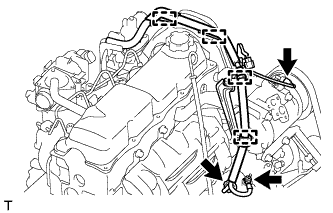
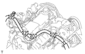
Attach the 4 wire harness clamps.
-
Install the generator wire with the nut.
- Torque:
- 9.8 N*m { 100 kgf*cm, 87 in.*lbf }
-
Install the terminal cap.
-
Connect the generator connector and cooler compressor connector.
-
for LHD:
Attach the 4 wire harness clamps.
-
-
INSTALL AIR CLEANER CASE ASSEMBLY
-
Установите корпус воздушного фильтра и закрепите его 3 болтами.
- Torque:
- 12 Н*м { 122 кгс*см, 9 фунт-сила-футов }
-
-
INSTALL AIR CLEANER FILTER ELEMENT SUB-ASSEMBLY
-
INSTALL RESONATOR WITH AIR CLEANER CAP SUB-ASSEMBLY
-
Вставьте петли крышки воздушного фильтра и шланг в корпус воздушного фильтра, а затем закрепите 4 откидных защелки.
-
Установите крышку воздушного фильтра и закрепите ее зажимом.
- Torque:
- 5,0 Н*м { 51 кгс*см, 44 фунт-сила-дюйма }
-
Закрепите зажим жгута проводов.
-
Подсоедините 2 зажима и разъем.
-
-
INSTALL FRONT FENDER APRON SEAL RH
-
Закрепите уплотнение фартука переднего крыла 4 фиксаторами.
-
-
ADD ENGINE COOLANT
-
Затяните пробку сливного крана радиатора вручную.
-
Затяните пробку сливного крана блока цилиндров.
- Torque:
- 13 Н*м { 130 кгс*см, 9 фунт-сила-футов }
-
Медленно заполните систему охлаждающей жидкостью двигателя.
Номинальный объем 8,6 литра (9,0 кварты США, 7,6 английской кварты) Note
Не доливайте простую воду вместо охлаждающей жидкости двигателя.
Tech Tips
-
Разрешается использовать только охлаждающую жидкость "Toyota Super Long Life Coolant" или аналогичную высококачественную охлаждающую жидкость на основе этиленгликоля (но не на силикатной, аминовой, нитритной или борнокислой основе), изготовленную по гибридной технологии органических кислот с длительным сроком годности (охлаждающая жидкость, изготовленная по гибридной технологии органических кислот, состоит из низкофосфатных соединений и органических кислот.)
-
Новые автомобили Toyota заправлены охлаждающей жидкостью "Toyota Super Long Life Coolant". Для замены рекомендуется использовать охлаждающую жидкость "Toyota Super Long Life Coolant" (розового цвета, предварительно смешанная, с концентрацией этиленгликоля около 50% и температурой замерзания -35°C (-31°F)).
-
-
Медленно залейте охлаждающую жидкость в расширительный бачок радиатора до отметки "FULL".
-
Установите пробку расширительного бачка.
-
Несколько раз сожмите рукой патрубки радиатора № 1 и № 2, а затем проверьте уровень охлаждающей жидкости. Если уровень охлаждающей жидкости недостаточен, добавьте жидкость.
-
Установите на место пробку радиатора.
-
Запустите двигатель и прогрейте его до открывания термостата.
Tech Tips
Время открывания термостата можно распознать, сжав шланг радиатора № 2 рукой и отметив момент, когда охлаждающая жидкость двигателя начнет поступать в шланг.
-
Поддерживайте частоту вращения коленчатого вала двигателя 2000–2500 об/мин.
Note
-
Убедитесь, что в расширительном бачке радиатора осталась охлаждающая жидкость.
-
Обратите внимание на стрелку датчика температуры охлаждающей жидкости. Убедитесь, что значение температуры не превышает норму.
-
В случае недостатка охлаждающей жидкости двигатель может закипеть или перегреться.
-
Если в расширительном бачке радиатора нет охлаждающей жидкости, сразу после запуска двигателя выполните следующие действия: 1) остановите двигатель, 2) подождите, пока охлаждающая жидкость остынет, и 3) долейте охлаждающую жидкость до линии "F".
-
Запустите двигатель, обеспечив частоту вращения коленчатого вала 2000 об/мин, и дайте ему поработать, пока уровень охлаждающей жидкости не стабилизируется.
-
-
Несколько раз сожмите патрубки радиатора № 1 и № 2 рукой, чтобы удалить воздух.
CAUTION:
-
Работайте в защитных перчатках. Нагретые участки деталей могут травмировать руки.
-
Будьте осторожны: патрубки радиатора горячие.
-
Не приближайте свои руки к вентилятору.
-
-
Остановите двигатель и подождите, пока охлаждающая жидкость остынет до температуры окружающего воздуха.
CAUTION:
Не снимайте пробку радиатора, пока двигатель и радиатор не остынут. Выброс горячей охлаждающей жидкости и пара под давлением может стать причиной серьезных ожогов.
-
Убедитесь, что уровень охлаждающей жидкости находится между отметками "LOW" и "FULL".
Если уровень охлаждающей жидкости ниже линии "Low", повторите все вышеперечисленные действия.
Если уровень охлаждающей жидкости выше уровня "FULL", слейте охлаждающую жидкость до уровня между отметками "FULL" и "LOW".
-
-
CONNECT CABLE TO NEGATIVE BATTERY TERMINAL
Note
When disconnecting the cable, some systems need to be initialized after the cable is reconnected Click here.
-
INSPECT FOR ENGINE COOLANT LEAK
CAUTION:
To avoid being burned, do not remove the radiator reservoir cap while the engine and radiator are still hot. Thermal expansion may cause hot engine coolant and steam to blow out from the radiator.
-
Fill the radiator with coolant and attach a radiator cap tester to the radiator.
-
Warm up the engine.
-
Using a radiator cap tester, increase the pressure inside the radiator to 123 kPa (1.3 kgf/cm2, 18 psi), and check that the pressure does not drop.
If the pressure drops, check the hoses, radiator or water pump for leaks. If no external leaks are found, check the heater core, cylinder block, and cylinder head.
-
-
INSPECT ENGINE IDLE SPEED
-
Warm up the engine.
-
When using the intelligent tester:
-
Connect the intelligent tester to the DLC3.
Idle speed 720 to 820 rpm Note
-
Turn all the electrical systems and the A/C off.
-
When checking the idling speed, the shift lever should be in neutral.
Tech Tips
Refer to the intelligent tester operator's manual for further details.
-
-
-
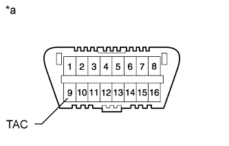
Text in Illustration *a Front View of DLC3 When not using an intelligent tester:
-
Using SST, connect the tachometer test probe to terminal 9 (TAC) of the DLC3.
- SST
- 09843-18040
-
Check the idle speed.
Standard idle speed 720 to 820 rpm Note
-
Turn all the electrical systems and the A/C off.
-
When checking the idling speed, the shift lever should be in neutral.
-
Confirm the terminal number before connecting them. Connecting the wrong terminal can be damage the engine.
-
-
-
-
INSPECT MAXIMUM ENGINE SPEED
-
Start the engine.
-
Fully depress the accelerator pedal.
-
Check the maximum speed.
Maximum engine speed 4850 to 4950 rpm
-
-
INSTALL NO. 1 ENGINE UNDER COVER SUB-ASSEMBLY
-
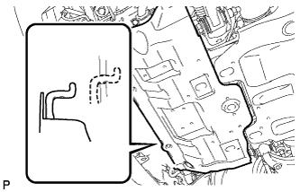
Присоедините защиту картера двигателя к кузову автомобиля, как показано на рисунке.
-
Вверните 4 болта.
- Torque:
- 29 Н*м { 296 кгс*см, 21 фунт-сила-фут }
-
-
INSTALL FRONT BUMPER COVER LOWER
-
Установите нижнюю облицовку переднего бампера и закрепите ее 5 болтами и фиксатором.
- Torque:
- 8,0 Н*м { 82 кгс*см, 71 фунт-сила-дюйм }
-
-
INSTALL UPPER RADIATOR SUPPORT SEAL
-
Установите верхнее уплотнение кронштейна радиатора и закрепите его 13 фиксаторами.
-