VEHICLE PROXIMITY NOTIFICATION SYSTEM (w/ Customization Function) The Sound does not Stop when The Engine is Operated or when The Shift Lever is in P
DESCRIPTION
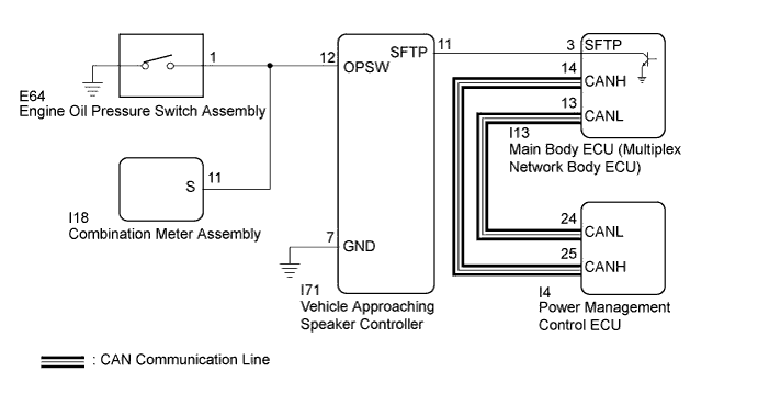
The vehicle approaching speaker controller receives engine oil pressure switch signals from the engine oil pressure switch assembly and P position switch signals from the main body ECU (multiplex network body ECU), and produces the warning sound from the vehicle approaching speaker assembly.
WIRING DIAGRAM
INSPECTION PROCEDURE
PROCEDURE
-
READ VALUE USING TECHSTREAM (Oil Pressure SW)
-
Connect the Techstream to the DLC3.
-
Turn the power switch on (IG).
-
Turn the Techstream on.
-
Enter the following menus: Body Electrical / Vehicle Proximity Notification System / Data List.
-
Read the Data List according to the display on the Techstream.
Vehicle Proximity Notification System Tester Display Measurement Item/Range Normal Condition Diagnostic Note Oil Pressure SW Oil pressure switch / OFF or ON OFF: Engine started
ON: Engine not started
- Result Result Proceed to The Techstream display changes according to engine operation A The Techstream display does not change according to engine operation B
B 
CHECK ENGINE OIL PRESSURE SWITCH ASSEMBLY (INPUT SIGNAL) Click here
A 
-
-
READ VALUE USING TECHSTREAM (Shift Position)
-
Connect the Techstream to the DLC3.
-
Turn the power switch on (IG).
-
Turn the Techstream on.
-
Enter the following menus: Body Electrical / Vehicle Proximity Notification System / Data List.
-
Read the Data List according to the display on the Techstream.
Vehicle Proximity Notification System Tester Display Measurement Item/Range Normal Condition Diagnostic Note Shift Position P position switch / Not Parking or Parking Not Parking or Parking - Result Result Proceed to The Techstream display changes according to the selected shift state A The Techstream display does not change according to the selected shift state B
B
CHECK VEHICLE APPROACHING SPEAKER CONTROLLER (SHIFT) Click here
A 
REPLACE VEHICLE APPROACHING SPEAKER CONTROLLER Click here
-
-
CHECK VEHICLE APPROACHING SPEAKER CONTROLLER (SHIFT)
-
Disconnect the I13 main body ECU (multiplex network body ECU) connector.
-
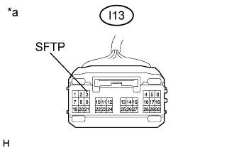
Text in Illustration *a Front view of wire harness connector
(to Main Body ECU (Multiplex Network Body ECU))
Measure the voltage according to the value(s) in the table below.
Standard Voltage Tester Connection Condition Specified Condition I13-3 (SFTP) - Body ground Power switch on (IG) 8 V or higher Power switch off Below 1 V
NG
CHECK HARNESS AND CONNECTOR (VEHICLE APPROACHING SPEAKER CONTROLLER - MAIN BODY ECU (MULTIPLEX NETWORK BODY ECU)) Click here
OK
-
-
CHECK MAIN BODY ECU (MULTIPLEX NETWORK BODY ECU)
-
Reconnect the I13 main body ECU (multiplex network body ECU) connector.
-
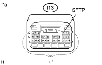
Text in Illustration *a Component with harness connected
(Main Body ECU (Multiplex Network Body ECU))
Measure the voltage according to the value(s) in the table below.
Standard Voltage Tester Connection Condition Specified Condition I13-3 (SFTP) - Body ground Power switch on (IG), shift lever in P Below 2.5 V Power switch on (IG), shift lever not in P 8 V or higher
NG 
REPLACE MAIN BODY ECU (MULTIPLEX NETWORK BODY ECU) Click here
OK
REPLACE VEHICLE APPROACHING SPEAKER CONTROLLER Click here
-
-
CHECK HARNESS AND CONNECTOR (VEHICLE APPROACHING SPEAKER CONTROLLER - MAIN BODY ECU (MULTIPLEX NETWORK BODY ECU))
-
Disconnect the I71 vehicle approaching speaker controller connector.
-
Measure the resistance according to the value(s) in the table below.
Standard Resistance Tester Connection Condition Specified Condition I71-11 (SFTP) - I13-3 (SFTP) Always Below 1 Ω I71-11 (SFTP) or I13-3 (SFTP) - Body ground Always 10 kΩ or higher
NG
REPAIR OR REPLACE HARNESS OR CONNECTOR
OK
REPLACE VEHICLE APPROACHING SPEAKER CONTROLLER Click here
-
-
CHECK ENGINE OIL PRESSURE SWITCH ASSEMBLY (INPUT SIGNAL)
-
Disconnect the I71 vehicle approaching speaker controller connector.
-
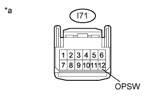
Text in Illustration *a Front view of wire harness connector
(to Vehicle Approaching Speaker Controller)
Measure the voltage according to the value(s) in the table below.
Standard Voltage Tester Connection Condition Specified Condition I71-12 (OPSW) - Body ground Idling* 8 V or higher Power switch on (IG) Below 2 V Tech Tips
*:Put the engine in inspection mode Click here.
NG
CHECK HARNESS AND CONNECTOR (VEHICLE APPROACHING SPEAKER CONTROLLER - ENGINE OIL PRESSURE SWITCH ASSEMBLY) Click here
OK
REPLACE VEHICLE APPROACHING SPEAKER CONTROLLER Click here
-
-
CHECK HARNESS AND CONNECTOR (VEHICLE APPROACHING SPEAKER CONTROLLER - ENGINE OIL PRESSURE SWITCH ASSEMBLY)
-
Disconnect the E64 engine oil pressure switch assembly connector.
-
Measure the resistance according to the value(s) in the table below.
Standard Resistance Tester Connection Condition Specified Condition I71-12 (OPSW) - E64-1 Always Below 1 Ω I71-12 (OPSW) or E64-1 - Body ground Always 10 kΩ or higher
NG
REPAIR OR REPLACE HARNESS OR CONNECTOR
OK
REPLACE ENGINE OIL PRESSURE SWITCH ASSEMBLY Click here
-