VEHICLE PROXIMITY NOTIFICATION SYSTEM (w/ Customization Function) There is No Sound Made
DESCRIPTION
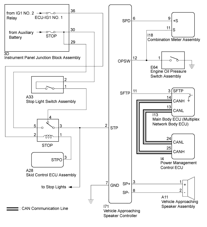
The vehicle approaching speaker controller receives stop light switch signals from the stop relay, vehicle speed signals from the combination meter assembly, engine oil pressure switch signals from the engine oil pressure switch assembly and P position switch signals from the main body ECU (multiplex network body ECU), and produces the warning sound from the vehicle approaching speaker assembly.
WIRING DIAGRAM
INSPECTION PROCEDURE
Note
Inspect the fuses for circuits related to this system before performing the following inspection procedure.
PROCEDURE
-
CHECK DTC OUTPUT
-
Connect the Techstream to the DLC3.
-
Turn the power switch on (IG).
-
Turn the Techstream on.
-
Enter the following menus: Body Electrical / Vehicle Proximity Notification System / Trouble Codes.
-
Check for DTCs.
Result Result Proceed to DTC B1350 is not output A DTC B1350 is output B Communication with the Techstream is not possible C
B 
GO TO DTC CHART B1350 Click here
C
GO TO OTHER DIAGNOSIS PROCEDURE (Communication between Vehicle Proximity Notification System and Diagnostic Tool is not Possible) Click here
A 
-
-
PERFORM ACTIVE TEST USING TECHSTREAM (Proximity Sound (Vehicle Stationary))
-
Connect the Techstream to the DLC3.
-
Turn the power switch on (IG).
-
Turn the Techstream on.
-
Enter the following menus: Body Electrical / Vehicle Proximity Notification System / Active Test.
-
Perform the Active Test according to the display on the Techstream.
Vehicle Proximity Notification System Tester Display Test Part Control Range Diagnostic Note Proximity Sound (Vehicle Stationary) Proximity sound (Vehicle stationary) OFF or ON Produces warning sound when vehicle is stopped Result Result Proceed to The warning sound is produced A The warning sound is not produced B
B 
CHECK HARNESS AND CONNECTOR (VEHICLE APPROACHING SPEAKER CONTROLLER - VEHICLE APPROACHING SPEAKER ASSEMBLY) Click here
A
-
-
READ VALUE USING TECHSTREAM (Stop Light SW)
-
Connect the Techstream to the DLC3.
-
Turn the power switch on (IG).
-
Turn the Techstream on.
-
Enter the following menus: Body Electrical / Vehicle Proximity Notification System / Data List.
-
Read the Data List according to the display on the Techstream.
Vehicle Proximity Notification System Tester Display Measurement Item/Range Normal Condition Diagnostic Note Stop Light SW Stop light switch / OFF or ON OFF: Brake pedal released
ON: Brake pedal depressed
- Result Result Proceed to The Techstream display changes according to brake pedal operation A The Techstream display does not change according to brake pedal operation B
B
CHECK STOP LIGHT OPERATION Click here
A
-
-
READ VALUE USING TECHSTREAM (Vehicle Speed)
-
Connect the Techstream to the DLC3.
-
Turn the power switch on (IG).
-
Turn the Techstream on.
-
Enter the following menus: Body Electrical / Vehicle Proximity Notification System / Data List.
-
Read the Data List according to the display on the Techstream.
Vehicle Proximity Notification System Tester Display Measurement Item/Range Normal Condition Diagnostic Note Vehicle Speed Vehicle speed / Min.: 0 km/h (0 mph), Max.: 255 km/h (158 mph) Almost the same as actual vehicle speed - Result Result Proceed to The Techstream display changes according to the vehicle speed A The Techstream display does not change according to the vehicle speed B
B
CHECK HARNESS AND CONNECTOR (VEHICLE APPROACHING SPEAKER CONTROLLER - COMBINATION METER ASSEMBLY) Click here
A
-
-
READ VALUE USING TECHSTREAM (Oil Pressure SW)
-
Connect the Techstream to the DLC3.
-
Turn the power switch on (IG).
-
Turn the Techstream on.
-
Enter the following menus: Body Electrical / Vehicle Proximity Notification System / Data List.
-
Read the Data List according to the display on the Techstream.
Vehicle Proximity Notification System Tester Display Measurement Item/Range Normal Condition Diagnostic Note Oil Pressure SW Oil pressure switch / OFF or ON OFF: Engine started
ON: Engine not started
- Result Result Proceed to The Techstream display changes according to engine operation A The Techstream display does not change according to engine operation B
B
CHECK ENGINE OIL PRESSURE SWITCH ASSEMBLY (INPUT SIGNAL) Click here
A
-
-
READ VALUE USING TECHSTREAM (Shift Position)
-
Connect the Techstream to the DLC3.
-
Turn the power switch on (IG).
-
Turn the Techstream on.
-
Enter the following menus: Body Electrical / Vehicle Proximity Notification System / Data List.
-
Read the Data List according to the display on the Techstream.
Vehicle Proximity Notification System Tester Display Measurement Item/Range Normal Condition Diagnostic Note Shift Position P position switch / Not Parking or Parking Not Parking or Parking - Result Result Proceed to The Techstream display changes according to the selected shift state A The Techstream display does not change according to the selected shift state B
B
CHECK VEHICLE APPROACHING SPEAKER CONTROLLER (SHIFT) Click here
A 
REPLACE VEHICLE APPROACHING SPEAKER CONTROLLER Click here
-
-
CHECK VEHICLE APPROACHING SPEAKER CONTROLLER (SHIFT)
-
Disconnect the I13 main body ECU (multiplex network body ECU) connector.
-
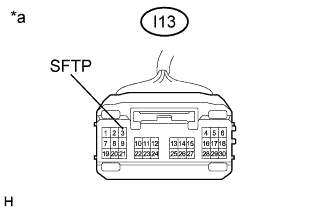
Text in Illustration *a Front view of wire harness connector
(to Main Body ECU (Multiplex Network Body ECU))
Measure the voltage according to the value(s) in the table below.
Standard Voltage Tester Connection Condition Specified Condition I13-3 (SFTP) - Body ground Power switch on (IG) 8 V or higher Power switch off Below 1 V
NG
CHECK HARNESS AND CONNECTOR (VEHICLE APPROACHING SPEAKER CONTROLLER - MAIN BODY ECU (MULTIPLEX NETWORK BODY ECU)) Click here
OK
-
-
CHECK MAIN BODY ECU (MULTIPLEX NETWORK BODY ECU)
-
Reconnect the I13 main body ECU (multiplex network body ECU) connector.
-
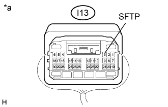
Text in Illustration *a Component with harness connected
(Main Body ECU (Multiplex Network Body ECU))
Measure the voltage according to the value(s) in the table below.
Standard Voltage Tester Connection Condition Specified Condition I13-3 (SFTP) - Body ground Power switch on (IG), shift lever in P Below 2.5 V Power switch on (IG), shift lever not in P 8 V or higher
NG
REPLACE MAIN BODY ECU (MULTIPLEX NETWORK BODY ECU) Click here
OK
REPLACE VEHICLE APPROACHING SPEAKER CONTROLLER Click here
-
-
CHECK HARNESS AND CONNECTOR (VEHICLE APPROACHING SPEAKER CONTROLLER - MAIN BODY ECU (MULTIPLEX NETWORK BODY ECU))
-
Disconnect the I71 vehicle approaching speaker controller connector.
-
Measure the resistance according to the value(s) in the table below.
Standard Resistance Tester Connection Condition Specified Condition I71-11 (SFTP) - I13-3 (SFTP) Always Below 1 Ω I71-11 (SFTP) or I13-3 (SFTP) - Body ground Always 10 kΩ or higher
NG
REPAIR OR REPLACE HARNESS OR CONNECTOR
OK
REPLACE VEHICLE APPROACHING SPEAKER CONTROLLER Click here
-
-
CHECK HARNESS AND CONNECTOR (VEHICLE APPROACHING SPEAKER CONTROLLER - VEHICLE APPROACHING SPEAKER ASSEMBLY)
-
Disconnect the I71 vehicle approaching speaker controller connector.
-
Disconnect the A11 vehicle approaching speaker assembly connector.
-
Measure the resistance according to the value(s) in the table below.
Standard Resistance Tester Connection Condition Specified Condition I71-3 (SP+) - A11-1 (+) Always Below 1 Ω I71-8 (SP-) - A11-2 (-) Always Below 1 Ω I71-3 (SP+) or A11-1 (+) - Body ground Always 10 kΩ or higher I71-8 (SP-) or A11-2 (-) - Body ground Always 10 kΩ or higher
NG
REPAIR OR REPLACE HARNESS OR CONNECTOR
OK
-
-
CHECK VEHICLE APPROACHING SPEAKER CONTROLLER
-
Reconnect the I71 vehicle approaching speaker controller connector.
-
Connect the Techstream to the DLC3.
-
Turn the power switch on (IG).
-
Turn the Techstream on.
-
Enter the following menus: Body Electrical / Vehicle Proximity Notification System / Active Test.
-
Perform the Active Test according to the display on the Techstream.
Vehicle Proximity Notification System Tester Display Test Part Control Range Diagnostic Note Proximity Sound (Vehicle Stationary) Proximity sound (Vehicle stationary) OFF or ON Produces warning sound when vehicle is stopped -
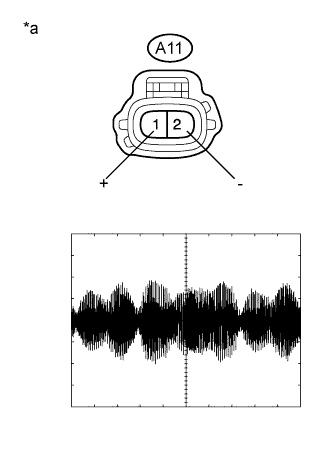
Text in Illustration *a Front view of wire harness connector
(to Vehicle Approaching Speaker Assembly)
Check the signal waveform according to the condition(s) in the table below.
Item Condition Tool setting 1 V/DIV., 200 ms./DIV. Vehicle condition Vehicle approaching speaker operating OK The waveform is similar to that shown in the illustration.
NG
REPLACE VEHICLE APPROACHING SPEAKER CONTROLLER Click here
OK
-
-
INSPECT VEHICLE APPROACHING SPEAKER ASSEMBLY
-
Remove the vehicle approaching speaker assembly Click here.
-
Inspect the vehicle approaching speaker assembly Click here.
NG
REPLACE VEHICLE APPROACHING SPEAKER ASSEMBLY Click here
OK
USE SIMULATION METHOD TO CHECK Click here
-
-
CHECK STOP LIGHT OPERATION
-
Check that the stop lights come on when the brake pedal is depressed, and go off when the brake pedal is released.
OK Condition Illumination Condition Brake pedal depressed On Brake pedal released Off
NG
GO TO LIGHTING SYSTEM Click here
OK
-
-
CHECK HARNESS AND CONNECTOR (VEHICLE APPROACHING SPEAKER CONTROLLER - STOP RELAY)
-
Disconnect the I71 vehicle approaching speaker controller connector.
-
Remove the stop relay.
-
Disconnect the M5 rear combination light assembly LH connector.
-
Disconnect the M6 rear combination light assembly RH connector.
-
Disconnect the S2 center stop light set connector.
-
Measure the resistance according to the value(s) in the table below.
Standard Resistance Tester Connection Condition Specified Condition I71-2 (STP) - Relay Terminal 3 Always Below 1 Ω I71-2 (STP) or Relay Terminal 3 - Body ground Always 10 kΩ or higher
NG
REPAIR OR REPLACE HARNESS OR CONNECTOR
OK
REPLACE VEHICLE APPROACHING SPEAKER CONTROLLER Click here
-
-
CHECK HARNESS AND CONNECTOR (VEHICLE APPROACHING SPEAKER CONTROLLER - COMBINATION METER ASSEMBLY)
-
Disconnect the I71 vehicle approaching speaker controller connector.
-
Disconnect the I18 combination meter assembly connector.
-
Measure the resistance according to the value(s) in the table below.
Standard Resistance Tester Connection Condition Specified Condition I71-6 (SPD) - I18-9 (+S) Always Below 1 Ω I71-6 (SPD) or I18-9 (+S) - Body ground Always 10 kΩ or higher
NG
REPAIR OR REPLACE HARNESS OR CONNECTOR
OK
-
-
CHECK COMBINATION METER ASSEMBLY
-
Reconnect the I71 vehicle approaching speaker controller connector.
-
Reconnect the I18 combination meter assembly connector.
-
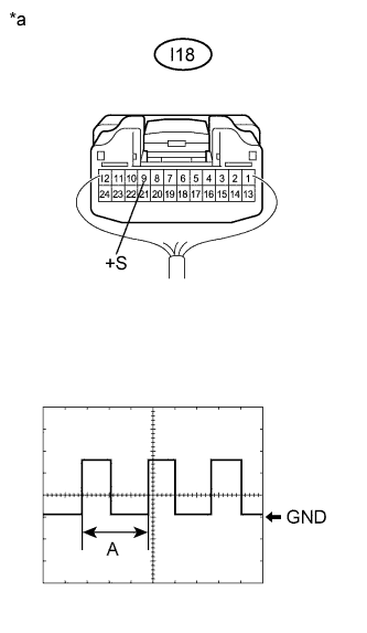
Text in Illustration *a Component with harness connected
(Combination Meter Assembly)
Check the input waveform.
-
Remove the combination meter assembly with the connector(s) still connected.
-
Connect an oscilloscope to terminal I18-9 (+S) and body ground.
-
Turn the power switch on (IG).
-
Turn a wheel slowly.
-
Check the signal waveform according to the condition(s) in the table below.
Item Condition Tool setting 5 V/DIV., 20 ms./DIV. Vehicle condition Power switch on (IG), wheel being rotated OK The waveform is similar to that shown in the illustration. Tech Tips
When the system is functioning normally, one wheel revolution generates 4 pulses. As the vehicle speed increases, the width indicated by (A) in the illustration narrows.
-
NG
GO TO METER / GAUGE SYSTEM Click here
OK
REPLACE VEHICLE APPROACHING SPEAKER CONTROLLER Click here
-
-
CHECK ENGINE OIL PRESSURE SWITCH ASSEMBLY (INPUT SIGNAL)
-
Disconnect the I71 vehicle approaching speaker controller connector.
-
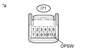
Text in Illustration *a Front view of wire harness connector
(to Vehicle Approaching Speaker Controller)
Measure the voltage according to the value(s) in the table below.
Standard Voltage Tester Connection Condition Specified Condition I71-12 (OPSW) - Body ground Idling* 8 V or higher Power switch on (IG) Below 2 V Tech Tips
*:Put the engine in inspection mode Click here.
NG
CHECK HARNESS AND CONNECTOR (VEHICLE APPROACHING SPEAKER CONTROLLER - ENGINE OIL PRESSURE SWITCH ASSEMBLY) Click here
OK
REPLACE VEHICLE APPROACHING SPEAKER CONTROLLER Click here
-
-
CHECK HARNESS AND CONNECTOR (VEHICLE APPROACHING SPEAKER CONTROLLER - ENGINE OIL PRESSURE SWITCH ASSEMBLY)
-
Disconnect the E64 engine oil pressure switch assembly connector.
-
Measure the resistance according to the value(s) in the table below.
Standard Resistance Tester Connection Condition Specified Condition I71-12 (OPSW) - E64-1 Always Below 1 Ω I71-12 (OPSW) or E64-1 - Body ground Always 10 kΩ or higher
NG
REPAIR OR REPLACE HARNESS OR CONNECTOR
OK
REPLACE ENGINE OIL PRESSURE SWITCH ASSEMBLY Click here
-