HAZARD WARNING SWITCH REMOVAL

-
PRECAUTION
Note
After turning the power switch off, waiting time may be required before disconnecting the cable from the negative (-) auxiliary battery terminal. Therefore, make sure to read the disconnecting the cable from the negative (-) auxiliary battery terminal notices before proceeding with work Click here.
-
REMOVE LUGGAGE TRIM SERVICE HOLE COVER
for Radio and Display Type with Intuitive Parking Assist System: Click here
for Navigation Receiver Type: Click here
-
DISCONNECT CABLE FROM AUXILIARY BATTERY NEGATIVE TERMINAL (for Radio and Display Type with Intuitive Parking Assist System)
Note
When disconnecting the cable, some systems need to be initialized after the cable is reconnected Click here.
-
DISCONNECT CABLE FROM AUXILIARY BATTERY NEGATIVE TERMINAL (for Navigation Receiver Type)
Note
When disconnecting the cable, some systems need to be initialized after the cable is reconnected Click here.
-
REMOVE REAR CONSOLE BOX ASSEMBLY
-
REMOVE BOX BOTTOM MAT
-
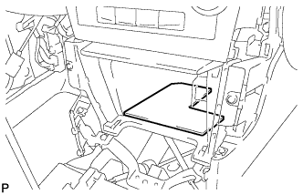
Remove the box bottom mat.
-
-
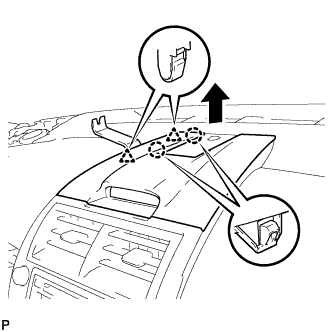
REMOVE UPPER CONSOLE PANEL SUB-ASSEMBLY
-
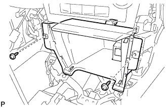
Remove the 2 screws <D> or <E>.
-
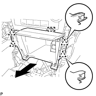
Disengage the 4 clips and guide as shown in the illustration.
-
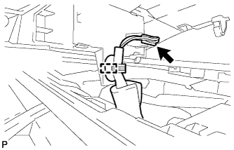
Disconnect each connector to remove the upper console panel sub-assembly.
-
-
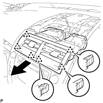
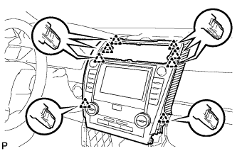
REMOVE CENTER INSTRUMENT CLUSTER FINISH PANEL ASSEMBLY
-
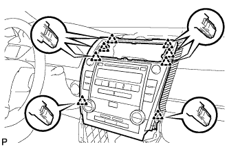
Using a moulding remover, disengage the 2 claws and 2 clips as shown in the illustration.
-
Using a moulding remover, disengage the 2 claws and 2 clips as shown in the illustration.
-
Disengage the 3 claws and 2 clips as shown in the illustration.
-
Disengage the clamp.
-
Disconnect the connector to remove the center instrument cluster finish panel assembly.
-
-
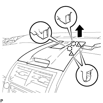
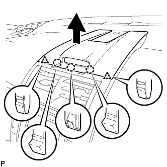
REMOVE NO. 2 INSTRUMENT PANEL REGISTER ASSEMBLY
-
Pull the No. 2 instrument panel register assembly in the direction indicated by the arrow to disengage the 6 clips to remove the No. 2 instrument panel register assembly.
-
-
REMOVE RADIO RECEIVER ASSEMBLY WITH AIR CONDITIONING CONTROL ASSEMBLY (for Radio Receiver Type)
-
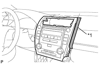
Text in Illustration *1 Protective Tape Apply protective tape to the area shown in the illustration.
-
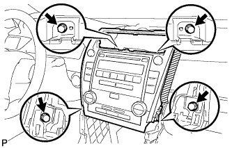
Remove the 4 bolts.
-
Pull the radio receiver assembly with air conditioning control assembly toward the rear of the vehicle and disengage the 8 clips.
-
Disconnect each connector and remove the radio receiver assembly with air conditioning control assembly.
-
-
REMOVE RADIO RECEIVER ASSEMBLY WITH AIR CONDITIONING CONTROL ASSEMBLY (for Radio and Display Type)
-
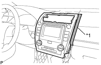
Text in Illustration *1 Protective Tape Apply protective tape to the areas shown in the illustration.
-
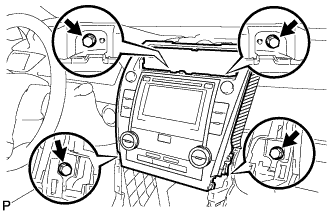
Remove the 4 bolts.
-
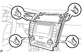
Pull the radio receiver assembly with air conditioning control assembly toward the rear of the vehicle and disengage the 8 clips.
-
Disconnect each connector and remove the radio receiver assembly with air conditioning control assembly.
Tech Tips
w/ Navigation System:Do not disconnect the extension module connector.
-
-
REMOVE NAVIGATION RECEIVER ASSEMBLY WITH AIR CONDITIONING CONTROL ASSEMBLY (for Navigation Receiver Type)
-
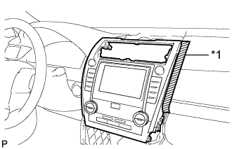
Text in Illustration *1 Protective Tape Apply protective tape to the areas shown in the illustration.
-
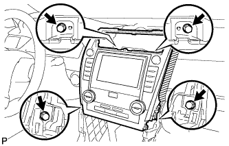
Remove the 4 bolts.
-
Pull the navigation receiver assembly with air conditioning control assembly toward the rear of the vehicle and disengage the 8 clips.
-
Disconnect each connector and remove the navigation receiver assembly with air conditioning control assembly.
-
-
REMOVE NO. 1 RADIO BRACKET (for Radio Receiver Type)
-
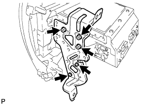
Remove the 5 screws and No. 1 radio bracket.
-
-
REMOVE NO. 2 RADIO BRACKET (for Radio Receiver Type)
-
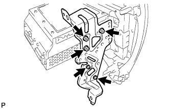
Remove the 5 screws and No. 2 radio bracket.
-
-
REMOVE NO. 1 RADIO BRACKET (for Radio and Display Type)
-
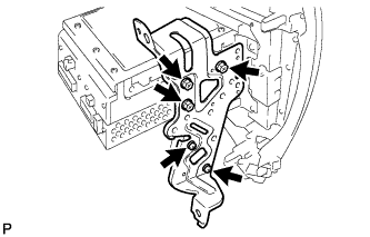
w/o Navigation System:
-
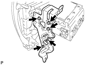
Remove the 5 screws and No. 1 radio bracket.
-
-
w/ Navigation System:
-
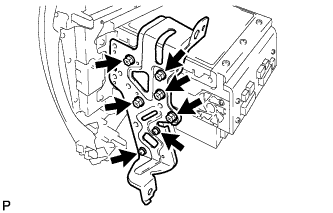
Remove the 7 screws and No. 1 radio bracket.
-
-
-
REMOVE NO. 2 RADIO BRACKET (for Radio and Display Type)
-
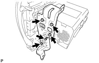
w/o Navigation System:
-
Remove the 5 screws and No. 2 radio bracket.
-
-
w/ Navigation System:
-
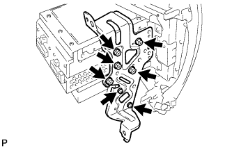
Remove the 7 screws and No. 2 radio bracket.
-
-
-
REMOVE NO. 1 RADIO RECEIVER BRACKET (for Radio and Display Type with Intuitive Parking Assist System)
-
Remove the 5 screws and No. 1 radio receiver bracket.
-
-
REMOVE NO. 2 RADIO RECEIVER BRACKET (for Radio and Display Type with Intuitive Parking Assist System)
-
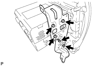
Remove the 5 screws and No. 2 radio receiver bracket.
-
-
REMOVE NO. 1 RADIO RECEIVER BRACKET (for Navigation Receiver Type)
-
Remove the 5 screws and No. 1 radio receiver bracket.
-
-
REMOVE NO. 2 RADIO RECEIVER BRACKET (for Navigation Receiver Type)
-
Remove the 5 screws and No. 2 radio receiver bracket.
-
-
REMOVE AIR CONDITIONING CONTROL ASSEMBLY (HAZARD SWITCH)
-
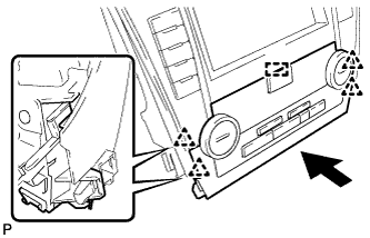
Disengage the 4 clips and guide, and remove the air conditioning control assembly as shown in the illustration.
-