HIGH INTENSITY DISCHARGE HEADLIGHT BULB INSTALLATION

Tech Tips
-
Use the same procedure for the RH and LH sides.
-
The procedure described below is for the LH side.
-
INSTALL DISCHARGE HEADLIGHT BULB
-
Set the discharge headlight bulb to the headlight unit.
Note
Do not touch the bulb glass.
-
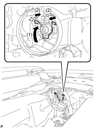
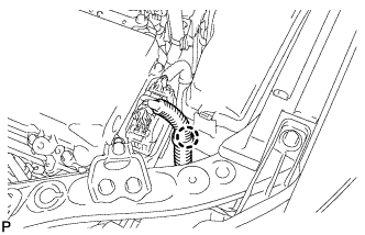
Lock the set spring to install the discharge headlight bulb as shown in the illustration.
-
-
INSTALL HEADLIGHT LIGHT CONTROL ECU SUB-ASSEMBLY
-
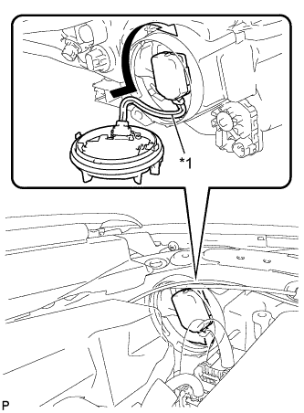
Turn the socket of the headlight light control ECU sub-assembly in the direction indicated by the arrow shown in the illustration to connect it.
Note
-
Check that the O-ring is installed on the headlight light control ECU sub-assembly.
-
Check that the O-ring is not damaged or contaminated with foreign matter. If there is any damage, replace the O-ring with a new one.
-
Do not pull the headlight light control ECU sub-assembly with the socket connected.
-
-
Check that the red line on the output harness is not twisted and store the harness in the headlight assembly securely so that the output harness is not pinched.
Text in Illustration *1 Red Line -
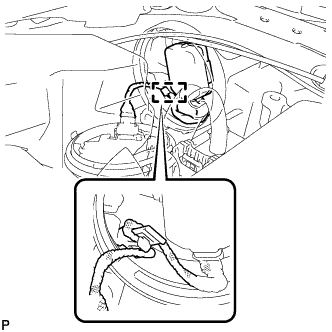
Engage the clamp.
-
for LH Side:
-
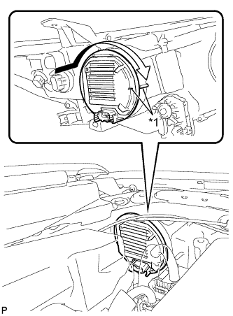
Text in Illustration *1 Lock Mark Turn the headlight light control ECU sub-assembly in the direction indicated by the arrow shown in the illustration until the lock marks are aligned to install it.
Note
-
To prevent incomplete installation, make sure to fully push in and turn the headlight light control ECU sub-assembly until the lock marks are aligned.
-
Do not apply excessive force using a tool.
-
-
Engage the claw and connect the wire harness.
-
-
for RH Side:
-
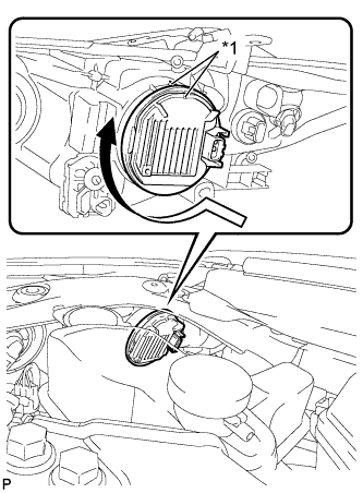
Text in Illustration *1 Lock Mark Turn the headlight light control ECU sub-assembly in the direction indicated by the arrow shown in the illustration until the lock marks are aligned to install it.
Note
-
To prevent incomplete installation, make sure to fully push in and turn the headlight light control ECU sub-assembly until the lock marks are aligned.
-
Do not apply excessive force using a tool.
-
-
-
Connect the connector.
-
-
CONNECT CABLE TO AUXILIARY BATTERY NEGATIVE TERMINAL
Note
When disconnecting the cable, some systems need to be initialized after the cable is reconnected Click here.
-
INSTALL LUGGAGE TRIM SERVICE HOLE COVER
-
Engage the claw to connect the luggage trim service hole cover.
-