REAR AIRBAG SENSOR REMOVAL

Tech Tips
-
Use the same procedure for the RH side and LH side.
-
The procedure listed below is for the LH side.
-
PRECAUTION
CAUTION:
Be sure to read Precaution thoroughly before servicing Click here.
Note
After turning the power switch off, waiting time may be required before disconnecting the cable from the negative (-) auxiliary battery terminal. Therefore, make sure to read the disconnecting the cable from the negative (-) auxiliary battery terminal notices before proceeding with work Click here.
-
REMOVE LUGGAGE TRIM SERVICE HOLE COVER
-
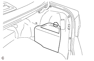
Disengage the claw to remove the luggage trim service hole cover.
-
-
DISCONNECT CABLE FROM NEGATIVE AUXILIARY BATTERY TERMINAL
CAUTION:
Wait at least 90 seconds after disconnecting the cable from the negative (-) auxiliary battery terminal to disable the SRS system.
Note
When disconnecting the cable, some systems need to be initialized after the cable is reconnected Click here.
-
REMOVE REAR SEAT CUSHION ASSEMBLY
-
Disengage the hook of the seat cushion from the vehicle body as shown in the illustration.
Note
Follow the instructions below carefully as the cushion frame can be deformed easily.
-
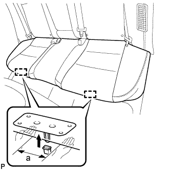
Choose a hook to disengage first. Place your hands near the hook as shown in the illustration. Then lift the seat cushion to disengage the hook.
Standard Measurement a 100 mm (3.94 in.) or less -
Repeat the step above for the other hook.
-
-
Remove the rear seat cushion assembly.
-
-
REMOVE REAR SEAT CUSHION LOCK HOOK
-
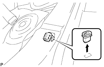
Disengage the claw and remove the rear seat cushion lock hook.
Note
Rear seat cushion lock hooks must not be reused.
Tech Tips
Use the same procedure for the RH side and the LH side.
-
-
REMOVE REAR SIDE SEATBACK ASSEMBLY
-
Disconnect the rear seat outer belt from the rear seat shoulder belt guide LH.
-
Disconnect the connector.
-
Remove the 2 bolts.
-
Disengage the hook and remove the rear side seatback assembly LH.
-
-
REMOVE SIDE NO. 2 AIRBAG SENSOR ASSEMBLY
-
Check that the power switch is off.
-
Check that the cable is disconnected from the negative (-) auxiliary battery terminal.
CAUTION:
Wait at least 90 seconds after disconnecting the cable from the negative (-) auxiliary battery terminal to disable the SRS system.
-
Disconnect the connector from the side No. 2 airbag sensor assembly.
Note
When disconnecting any airbag connector, take care not to damage the airbag wire harness.
-
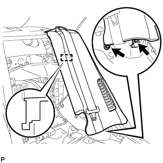
Push down the white housing lock and slide the yellow CPA. (At this time, the connector cannot be disconnected yet.)
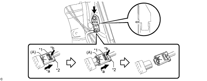
Text in Illustration *1 White Housing Lock *2 Yellow CPA *a Slide *b Push -
Push down the white housing lock again and disconnect the connector.
Note
Do not push down the part (A) shown in the illustration when disconnecting the connector.
-
-
Remove the bolt and side No. 2 airbag sensor assembly from the vehicle body.
Note
Loosen the bolt while holding the side No. 2 airbag sensor assembly because the side No. 2 airbag sensor assembly pin (stopper) is easily damaged.
-
After disconnecting the connector, check that the position of the white housing lock is correct as shown in the illustration.
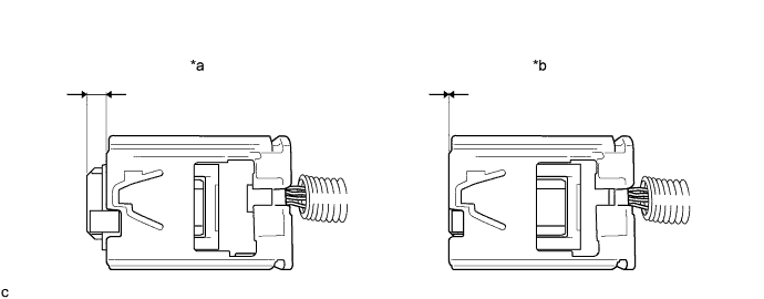
Text in Illustration *a Correct *b Incorrect
-