KNEE AIRBAG ASSEMBLY (for Driver Side) INSTALLATION

-
INSTALL LOWER NO. 1 INSTRUMENT PANEL AIRBAG ASSEMBLY
-
Check that the power switch is off.
-
Check that the cable is disconnected from the negative (-) auxiliary battery terminal.
CAUTION:
Wait at least 90 seconds after disconnecting the cable from the negative (-) auxiliary battery terminal to disable the SRS system.
-
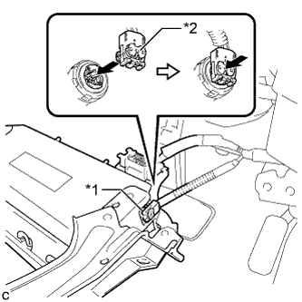
Text in Illustration *1 Airbag Connector *2 Airbag Connector Lock Connect the airbag connector to the lower No. 1 instrument panel airbag assembly.
Note
When connecting any airbag connector, take care not to damage the airbag wire harness.
-
Push in the lock to install the airbag connector.
-
Temporarily install the lower No. 1 instrument panel airbag assembly with the 2 hooks.
-
Engage the 2 claws to install the DLC3.
-
Install the 4 bolts.
- Torque:
- 10 N*m { 102 kgf*cm, 7 ft.*lbf }
Note
Confirm that the lower No. 1 instrument panel airbag assembly is installed securely without any excessive gaps and is not protruding outward.
-
-
INSTALL LOWER NO. 1 INSTRUMENT PANEL FINISH PANEL ASSEMBLY
-
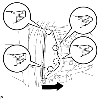
Engage the 4 claws, 9 clips and 3 guides.
-
Install the lower No. 1 instrument panel finish panel assembly with the bolt <C> and screw <D> or <E>.
-
-
CONNECT HOOD LOCK CONTROL LEVER SUB-ASSEMBLY
-
Engage the claw and 2 guides to connect the hood lock control lever sub-assembly.
-
-
INSTALL INSTRUMENT SIDE PANEL LH
-
Engage the 3 guides.
-
Engage the 4 claws to install the instrument side panel LH as shown in the illustration.
-
-
CONNECT FRONT DOOR OPENING TRIM WEATHERSTRIP LH
-
INSTALL COWL SIDE TRIM SUB-ASSEMBLY LH
-
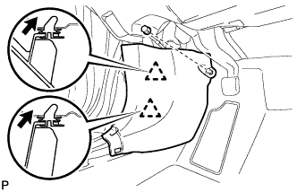
Insert the 2 clips in the direction indicated by the arrows shown in the illustration to engage them.
-
Install the cowl side trim sub-assembly LH with the clip.
-
-
INSTALL FRONT DOOR SCUFF PLATE LH
-
Engage the 10 claws to install the front door scuff plate LH.
-
-
CONNECT CABLE TO NEGATIVE AUXILIARY BATTERY TERMINAL
Note
When disconnecting the cable, some systems need to be initialized after the cable is reconnected Click here.
-
INSTALL LUGGAGE TRIM SERVICE HOLE COVER
-
Engage the claw to connect the luggage trim service hole cover.
-
-
PERFORM DIAGNOSTIC SYSTEM CHECK
-
INSPECT SRS WARNING LIGHT