THEFT DETERRENT SYSTEM Glass Breakage Sensor Circuit
DESCRIPTION
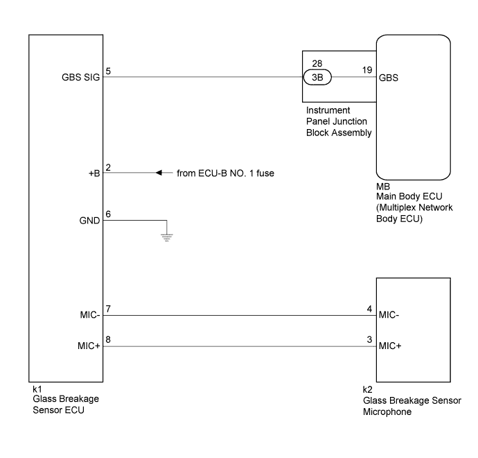
When the glass breakage sensor detects that any door glass is tapped or broken, the theft deterrent system switches from the armed state to the alarm sounding state.
WIRING DIAGRAM
INSPECTION PROCEDURE
Note
Inspect the fuses for circuits related to this system before performing the following inspection procedure.
PROCEDURE
-
INSPECT INSTRUMENT PANEL JUNCTION BLOCK ASSEMBLY
-
Remove the main body ECU (multiplex network body ECU) Click here.
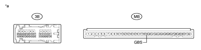
Text in Illustration *a Component without harness connected
(Instrument Panel Junction Block Assembly)
- - -
Disconnect the 3B instrument panel junction block assembly connector.
-
Measure the resistance according to the value(s) in the table below.
Standard Resistance Tester Connection Condition Specified Condition 3B-28 - MB-19 (GBS) Always Below 1 Ω
NG 
REPLACE INSTRUMENT PANEL JUNCTION BLOCK ASSEMBLY Click here
OK 
-
-
CHECK HARNESS AND CONNECTOR (AUXILIARY BATTERY - GLASS BREAKAGE SENSOR ECU - BODY GROUND)
-
Disconnect the k1 glass breakage sensor ECU connector.
-
Measure the voltage and resistance according to the value(s) in the table below.
Standard Voltage Tester Connection Condition Specified Condition k1-2 (+B) - Body ground Always 11 to 14 V Standard Resistance Tester Connection Condition Specified Condition k1-6 (GND) - Body ground Always Below 1 Ω
NG
REPAIR OR REPLACE HARNESS OR CONNECTOR
OK
-
-
CHECK HARNESS AND CONNECTOR (INSTRUMENT PANEL JUNCTION BLOCK ASSEMBLY - GLASS BREAKAGE SENSOR ECU)
-
Measure the resistance according to the value(s) in the table below.
Standard Resistance Tester Connection Condition Specified Condition k1-5 (GBS SIG) - 3B-28 Always Below 1 Ω k1-5 (GBS SIG) - Body ground Always 10 kΩ or higher
NG
REPAIR OR REPLACE HARNESS OR CONNECTOR
OK
-
-
CHECK HARNESS AND CONNECTOR (GLASS BREAKAGE SENSOR ECU - GLASS BREAKAGE SENSOR MICROPHONE)
-
Disconnect the k2 glass breakage sensor microphone connector.
-
Measure the resistance according to the value(s) in the table below.
Standard Resistance Tester Connection Condition Specified Condition k1-7 (MIC-) - k2-4 (MIC-) Always Below 1 Ω k1-7 (MIC-) - Body ground Always 10 kΩ or higher k1-8 (MIC+) - k2-3 (MIC+) Always Below 1 Ω k1-8 (MIC+) - Body ground Always 10 kΩ or higher
NG
REPAIR OR REPLACE HARNESS OR CONNECTOR
OK
-
-
REPLACE GLASS BREAKAGE SENSOR MICROPHONE
-
Replace the glass breakage sensor microphone Click here.
NEXT
-
-
CHECK GLASS BREAKAGE SENSOR
-
Check the operation of the glass breakage sensor Click here.
OK When tapping on the glass breakage sensor microphone with your finger, the alarm function operates.
NG 
REPLACE GLASS BREAKAGE SENSOR ECU Click here
OK 
END (GLASS BREAKAGE SENSOR MICROPHONE WAS DEFECTIVE)
-
-
REPLACE GLASS BREAKAGE SENSOR ECU
-
Replace the glass breakage sensor ECU Click here.
NEXT
-
-
CHECK GLASS BREAKAGE SENSOR
-
Check the operation of the glass breakage sensor Click here.
OK When tapping on the glass breakage sensor microphone with your finger, the alarm function operates.
NG
REPLACE MAIN BODY ECU (MULTIPLEX NETWORK BODY ECU) Click here
OK
END (GLASS BREAKAGE SENSOR ECU WAS DEFECTIVE)
-