WIRELESS DOOR LOCK CONTROL SYSTEM, Diagnostic DTC:B1242

| DTC Code | DTC Name |
|---|---|
| B1242 | Wireless Door Lock Tuner Circuit Malfunction |
DESCRIPTION
The door control receiver is used to receive radio waves relating to the entry functions of the electrical key transmitter sub-assembly. The certification ECU (smart key ECU assembly) decodes the requested electrical key transmitter sub-assembly by identifying a key code based on the radio waves received via the door control receiver. The door control receiver receives a signal from the electrical key transmitter sub-assembly and sends signals to the main body ECU (multiplex network body ECU) through the certification ECU (smart key ECU assembly). The certification ECU (smart key ECU assembly) then sends a command, according to the requested operation, to each ECU (ex. if door lock operation is requested, the certification ECU (smart key ECU assembly) sends a door lock command to the main body ECU (multiplex network body ECU)).
| DTC No. | DTC Detection Condition | Trouble Area |
|---|---|---|
| B1242 |
|
|
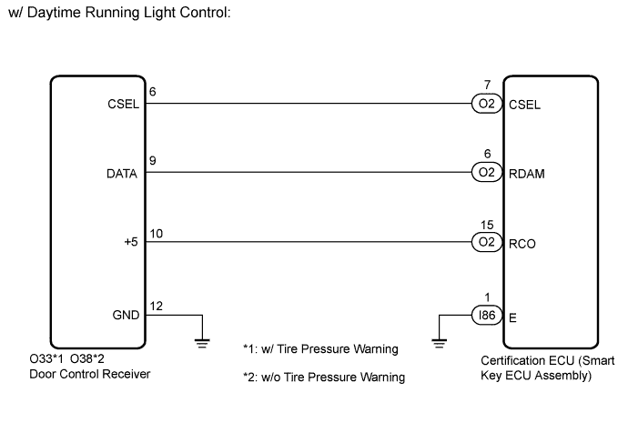
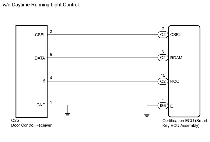
WIRING DIAGRAM
INSPECTION PROCEDURE
Note
-
When replacing or inspecting the door control receiver and wire harness, do not change the position or length of the wire harness. If the wire harness is too close to the door control receiver, smart and wireless function performance may be affected.
-
Before performing the inspection, check that there are no problems related to the CAN communication system Click here.
-
When replacing the door control receiver, read the transmitter IDs (tire pressure warning system) stored in the old ECU using the Techstream and write them down before removal Click here.*
-
It is necessary to perform registration Click here of the transmitter IDs into the door control receiver if the door control receiver has been replaced.*
-
This DTC is not detected within 10 seconds after the power switch turned to off from on (IG).
-
*: w/ Tire Pressure Warning System
PROCEDURE
-
CHECK CERTIFICATION ECU (SMART KEY ECU ASSEMBLY)
-
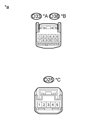
Text in Illustration *A w/ Daytime Running Light Control and w/ Tire Pressure Warning *B w/ Daytime Running Light Control and w/o Tire Pressure Warning *C w/o Daytime Running Light Control *a Front view of wire harness connector
(to Door control receiver)
Disconnect the door control receiver connector.
-
Measure the resistance and voltage according to the value(s) in the table below.
Standard Voltage w/ Daytime Running Light Control Tester Connection Condition Specified Condition O33-10 (+5) - O33-12 (GND)*1
O38-10 (+5) - O38-12 (GND)*2
Power switch off, all doors closed and electrical key transmitter sub-assembly switch not pressed → electrical key transmitter sub-assembly switch pressed Below 1 V → 4.5 to 5.5 V
(Pulse generation)
O33-9 (DATA) - O33-12 (GND)*1
O38-9 (DATA) - O38-12 (GND)*2
Power switch off 11 to 14 V pulse generation at regular intervals Standard Resistance w/ Daytime Running Light Control Tester Connection Condition Specified Condition O33-12 (GND) - Body ground*1
O38-12 (GND) - Body ground*2
Always Below 1 Ω
-
*1: w/ Tire Pressure Warning
-
*2: w/o Tire Pressure Warning
Standard Voltage w/o Daytime Running Light Control Tester Connection Condition Specified Condition O25-4 (+5) - O25-12 (GND) Power switch off, all doors closed and electrical key transmitter sub-assembly switch not pressed → electrical key transmitter sub-assembly switch pressed Below 1 V → 4.5 to 5.5 V
(Pulse generation)
O25-9 (DATA) - O25-12 (GND) Power switch off 11 to 14 V pulse generation at regular intervals Standard Resistance w/o Daytime Running Light Control Tester Connection Condition Specified Condition O25-12 (GND) - Body ground Always Below 1 Ω Result Result Proceed to NG A OK (w/ Daytime Running Light Control and w/ Tire Pressure Warning System) B OK (w/o Daytime Running Light Control or w/o Tire Pressure Warning System) C -
B 
REPLACE DOOR CONTROL AND TIRE PRESSURE MONITORING SYSTEM RECEIVER ASSEMBLY Click here
C
REPLACE DOOR CONTROL RECEIVER Click here
A 
-
-
CHECK HARNESS AND CONNECTOR (DOOR CONTROL RECEIVER - CERTIFICATION ECU (SMART KEY ECU ASSEMBLY))
-
Disconnect the O2 and I86 certification ECU (smart key ECU assembly) connectors.
-
Measure the resistance according to the value(s) in the table below.
Standard Resistance w/ Daytime Running Light Control Tester Connection Condition Specified Condition O2-7 (CSEL) - O33-6 (CSEL)*1
O2-7 (CSEL) - O38-6 (CSEL)*2
Always Below 1 Ω O2-6 (RDAM) - O33-9 (DATA)*1
O2-6 (RDAM) - O38-9 (DATA)*2
Always Below 1 Ω O2-15 (RCO) - O33-10 (+5)*1
O2-15 (RCO) - O38-10 (+5)*2
Always Below 1 Ω I86-1 (E) - Body ground Always Below 1 Ω O33-12 (GND) - Body ground*1
O38-12 (GND) - Body ground*2
Always Below 1 Ω O2-7 (CSEL) or O33-6 (CSEL) - Body ground*1
O2-7 (CSEL) or O38-6 (CSEL) - Body ground*2
Always 10 kΩ or higher O2-6 (RDAM) or O33-9 (DATA) - Body ground*1
O2-6 (RDAM) or O38-9 (DATA) - Body ground*2
Always 10 kΩ or higher O2-15 (RCO) or O33-10 (+5) - Body ground*1
O2-15 (RCO) or O38-10 (+5) - Body ground*2
Always 10 kΩ or higher
-
*1: w/ Tire Pressure Warning
-
*2: w/o Tire Pressure Warning
Standard Resistance w/o Daytime Running Light Control Tester Connection Condition Specified Condition O2-7 (CSEL) - O25-2 (CSEL) Always Below 1 Ω O2-6 (RDAM) - O25-5 (DATA) Always Below 1 Ω O2-15 (RCO) - O25-4 (+5) Always Below 1 Ω I86-1 (E) - Body ground Always Below 1 Ω O25-1 (GND) - Body ground Always Below 1 Ω O2-7 (CSEL) or O25-2 (CSEL) - Body ground Always 10 kΩ or higher O2-6 (RDAM) or O25-5 (DATA) - Body ground Always 10 kΩ or higher O2-15 (RCO) or O25-4 (+5) - Body ground Always 10 kΩ or higher -
NG
REPAIR OR REPLACE HARNESS OR CONNECTOR
OK 
REPLACE CERTIFICATION ECU (SMART KEY ECU ASSEMBLY) Click here
-