CAN COMMUNICATION SYSTEM SYSTEM DIAGRAM

-
OVERALL CAN BUS DIAGRAM
-
The CAN communication system is composed of 3 buses.
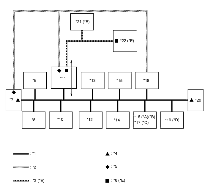
Text in Illustration *A for Navigation receiver type *B for Radio and display type (w/ Intuitive parking assist system) *C for Radio and display type (w/o Intuitive parking assist system) *D w/ Intuitive parking assist system *E w/ Blind spot monitor system - - *1 V Bus *2 Sub Bus 15 *3 Sub Bus 11 *4 V Bus Terminating Resistor *5 Sub Bus 15 Terminating Resistor *6 Sub Bus 11 Terminating Resistor *7 ECM
(for V Bus and Sub Bus 15)
*8 Steering Sensor
(for V Bus)
*9 Main Body ECU (Multiplex Network Body ECU)
(for V Bus)
*10 DLC3
(for V Bus)
*11 Power Management Control ECU
(for V Bus, Sub Bus 11 and Sub Bus 15)
*12 Air Conditioning Amplifier Assembly
(for V Bus)
*13 Airbag Sensor Assembly
(for V Bus)
*14 Smart Key ECU Assembly (Certification ECU)
(for V Bus)
*15 Power Steering ECU Assembly
(for V Bus)
*16 Navigation ECU Sub-assembly
(for V Bus)
*17 Radio and Display Receiver Assembly
(for V Bus)
*18 Brake Booster with Master Cylinder Assembly (Skid Control ECU)
(for V Bus and Sub Bus 15)
*19 Clearance Warning ECU Assembly
(for V Bus)
*20 Combination Meter Assembly
(for V Bus)
*21 Blind Spot Monitor Sensor RH
(for Sub Bus 11)
*22 CAN No. 4 J/C
(for Sub Bus 11)
Tech Tips
-
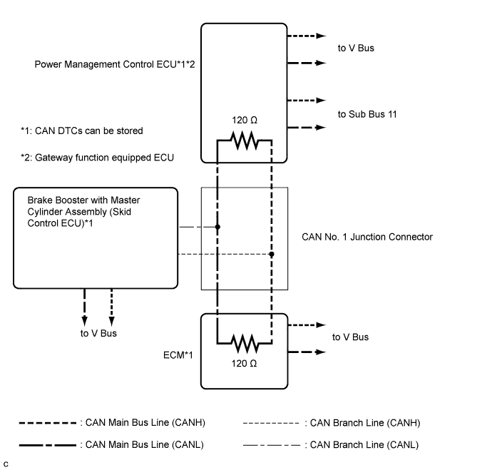
The power management control ECU functions as a gateway between the V bus and sub bus 11.
-
Refer to the following bus wiring diagrams for details.
-
-
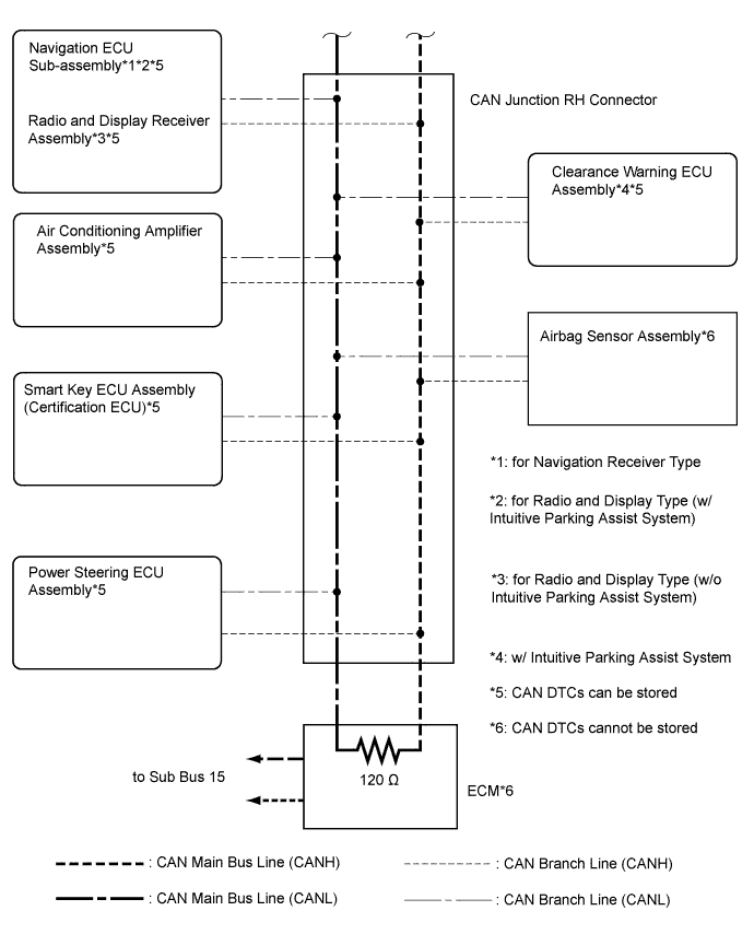
V BUS
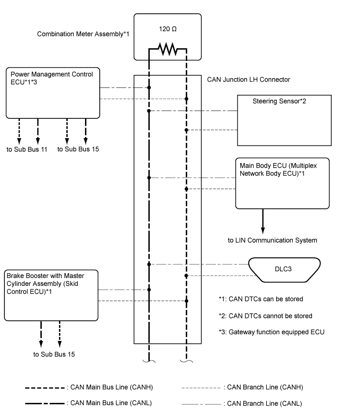
Tech Tips
The CAN communication system connects to other network via ECUs that function as a gateway Click here.
-
SUB BUS 11 (w/ BLIND SPOT MONITOR SYSTEM)
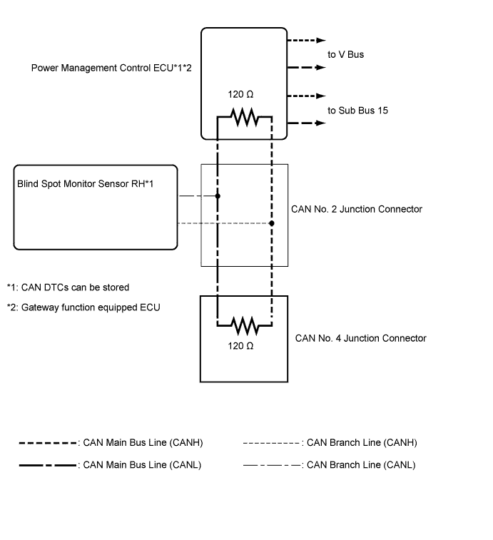
-
SUB BUS 15