LIN COMMUNICATION SYSTEM, Diagnostic DTC:B126A

| DTC Code | DTC Name |
|---|---|
| B126A | Remote Engine Starter ECU Communication Stop |
DESCRIPTION
The main body ECU (multiplex network body ECU) communicates with the accessory ECUs via BERKES communication.
These DTCs are stored when communication between the main body ECU (multiplex network body ECU) and accessory ECU stops for 10 seconds or more.
| DTC No. | DTC Detection Condition | Trouble Area |
|---|---|---|
| B126A | No communication between main body ECU (multiplex network body ECU) and accessory ECU for 10 seconds or more. |
|
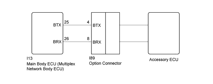
WIRING DIAGRAM
INSPECTION PROCEDURE
Note
-
When using the Techstream to troubleshoot with the power switch off: Connect the Techstream to the DLC3, and turn the courtesy switch on and off at 1.5-second intervals until communication between the Techstream and vehicle begins.
-
Before starting repair, check that the power source system of the accessory ECU is not malfunctioning.
-
When the main body ECU (multiplex network body ECU) is replaced with a new part and the cable is reconnected to the negative (-) auxiliary battery terminal, the power switch condition will be on (IG). Also, when the cable is disconnected and reconnected to the negative (-) auxiliary battery terminal, the condition will be the same as it was before the cable was disconnected.
PROCEDURE
-
CHECK HARNESS AND CONNECTOR (MAIN BODY ECU - OPTION CONNECTOR)
-
Disconnect the I13 main body ECU (multiplex network body ECU) connector.
-
Disconnect the I89 option connector.
-
Measure the resistance according to the value(s) in the table below.
Standard Resistance Tester Connection Condition Specified Condition I13-25 (BTX) - I89-4 (BTX) Always Below 1 Ω I13-26 (BRX) - I89-8 (BRX) Always Below 1 Ω I13-26 (BRX) - Body ground Always 10 kΩ or higher I89-8 (BRX) - Body ground Always 10 kΩ or higher
NG 
REPAIR OR REPLACE HARNESS OR CONNECTOR
OK 
-
-
REPLACE OPTION CONNECTOR
-
Replace the option connector.
NEXT
-
-
CHECK DTC OUTPUT
-
Clear the DTC Click here.
-
Recheck for DTCs.
OK DTC B126A is not output.
NG
REPLACE MAIN BODY ECU (MULTIPLEX NETWORK BODY ECU) Click here
OK 
END (OPTION CONNECTOR ECU WAS DEFECTIVE)
-