INTUITIVE PARKING ASSIST SYSTEM Clearance Sonar Main Switch Circuit
DESCRIPTION
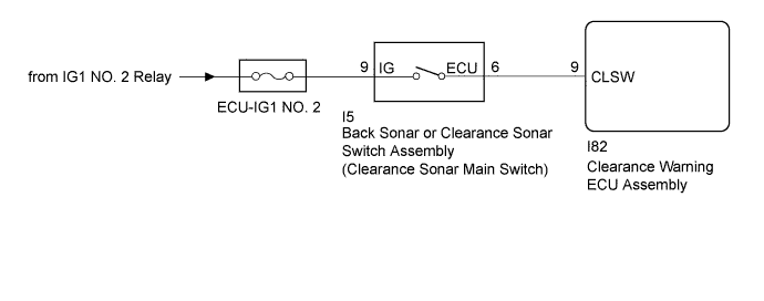
The back sonar or clearance sonar switch assembly is installed at the base of the driver side of the instrument panel.
When the clearance sonar main switch is turned on, an on signal is sent to the clearance warning ECU assembly. The intuitive parking assist system operates according to this signal.
WIRING DIAGRAM
INSPECTION PROCEDURE
Note
Inspect the fuse for circuits related to this system before performing the following inspection procedure.
PROCEDURE
-
READ VALUE USING TECHSTREAM
-
Connect the Techstream to the DLC3.
-
Turn the power switch on (IG).
-
Turn the Techstream on.
-
Enter the following menus: Body Electrical / Intuitive P/A / Data List.
-
According to the display on the Techstream, read the Data List.
Intuitive P/A Tester Display Measurement Item/Range Normal Condition Diagnostic Note Main Switch Clearance sonar main switch/OFF or ON OFF: Clearance sonar main switch off
ON: Clearance sonar main switch on
- Intuitive P/A ECU Type Type of intuitive P/A ECU/Normal Normal: Normal clearance sonar type - Result Result Proceed to Both of the following conditions are met:
-
The display changes as shown above when the clearance sonar main switch is operated.
-
"Normal" is displayed.
A "Normal" is not displayed. B Both of the following conditions are met:
-
The display does not change as shown above when the clearance sonar main switch is operated.
-
"Normal" is displayed.
C -
B 
REPLACE CLEARANCE WARNING ECU ASSEMBLY Click here
C 
INSPECT BACK SONAR OR CLEARANCE SONAR SWITCH ASSEMBLY Click here
A 
PROCEED TO NEXT SUSPECTED AREA SHOWN IN PROBLEM SYMPTOMS TABLE Click here
-
-
INSPECT BACK SONAR OR CLEARANCE SONAR SWITCH ASSEMBLY
-
Remove the back sonar or clearance sonar switch assembly Click here.
-
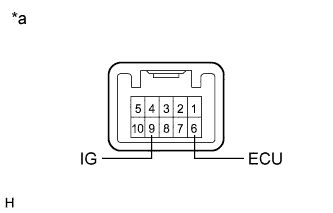
Text in Illustration *a Component without harness connected
(Back Sonar or Clearance Sonar Switch Assembly)
Measure the resistance according to the value(s) in the table below.
Standard Resistance Tester Connection Switch Condition Specified Condition 9 (IG) - 6 (ECU) Clearance sonar main switch on Below 1 Ω 9 (IG) - 6 (ECU) Clearance sonar main switch off 10 kΩ or higher
NG
REPLACE BACK SONAR OR CLEARANCE SONAR SWITCH ASSEMBLY Click here
OK 
-
-
CHECK HARNESS AND CONNECTOR (BACK SONAR OR CLEARANCE SONAR SWITCH ASSEMBLY POWER SOURCE)
-
Measure the voltage according to the value(s) in the table below.
Standard Voltage Tester Connection Condition Specified Condition I5-9 (IG) - Body ground Power switch on (IG) 11 to 14 V I5-9 (IG) - Body ground Power switch off Below 1 V
NG
REPAIR OR REPLACE HARNESS OR CONNECTOR
OK
-
-
CHECK HARNESS AND CONNECTOR (BACK SONAR OR CLEARANCE SONAR SWITCH ASSEMBLY - CLEARANCE WARNING ECU ASSEMBLY)
-
Disconnect the I82 connector from the NO. 1 ultrasonic sensor.
-
Measure the resistance according to the value(s) in the table below.
Standard Resistance Tester Connection Condition Specified Condition I82-9 (CLSW) - I5-6 (ECU) Always Below 1 Ω I82-9 (CLSW) - Body ground Always 10 kΩ or higher
NG
REPAIR OR REPLACE HARNESS OR CONNECTOR
OK
REPLACE CLEARANCE WARNING ECU ASSEMBLY Click here
-