NAVIGATION SYSTEM (for Navigation Receiver Type) AVC-LAN Circuit
DESCRIPTION
Each unit of the navigation system connected to the AVC-LAN (communication bus) transfers the switch signals using the AVC-LAN.
If a short to +B or short to ground occurs in the AVC-LAN, the navigation system will not function normally because communication is not possible.
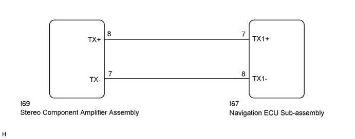
WIRING DIAGRAM
INSPECTION PROCEDURE
Note
After replacing the navigation ECU sub-assembly of vehicles subscribed to pay-type satellite radio broadcasts, registration of the XM radio ID is necessary.
Tech Tips
The navigation ECU sub-assembly is the master unit.
PROCEDURE
-
INSPECT NAVIGATION ECU SUB-ASSEMBLY
-
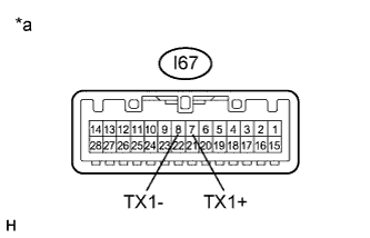
Text in Illustration *a Component without harness connected
(Navigation ECU Sub-assembly)
Disconnect the navigation ECU sub-assembly connector.
-
Measure the resistance according to the value(s) in the table below.
Standard Resistance Tester Connection Condition Specified Condition I67-7 (TX1+) - I67-8 (TX1-) Always 60 to 80 Ω
NG 
REPLACE NAVIGATION ECU SUB-ASSEMBLY Click here
OK 
-
-
CHECK HARNESS AND CONNECTOR (AVC-LAN CIRCUIT)
-
Disconnect the navigation ECU sub-assembly connector.
-
Disconnect the stereo component amplifier assembly connector.
-
Measure the resistance according to the value(s) in the table below.
Standard Resistance Tester Connection Condition Specified Condition I69-8 (TX+) - I67-7 (TX1+) Always Below 1 Ω I69-7 (TX-) - I67-8 (TX1-) Always Below 1 Ω I69-8 (TX+) - Body ground Always 10 kΩ or higher I69-7 (TX-) - Body ground Always 10 kΩ or higher
NG
REPAIR OR REPLACE HARNESS OR CONNECTOR
OK
-
-
INSPECT MALFUNCTIONING PARTS
-
Disconnect and reconnect each slave unit one by one until the master unit returns to normal operation.
Tech Tips
-
Check all slave units.
-
If disconnecting a slave unit causes the master unit to return to normal operation, the slave unit is defective and should be replaced.
OK Master unit returns to normal operation. -
NG
REPLACE NAVIGATION ECU SUB-ASSEMBLY Click here
OK 
REPLACE MALFUNCTIONING PARTS
-